


 Accurate
Miniatures 1/48 Grumman F3F-1
Accurate
Miniatures 1/48 Grumman F3F-1
By Michael Benolkin
Background
[Note: If you read last month's in-box review of this kit then you've already read the F3F's background summary.]
As naval aviation was getting more firmly established in the 1930s, the Grumman company was already establishing itself as the builder of Navy fighters. From the original FF-1 to the F-14D Tomcat, with names like Wildcat, Hellcat, Tigercat, Panther, Cougar, and Tiger distributed in-between, the Grumman Corporation became synonymous with Naval Aviation.
In the mid-1930s, aviation in general was in transition from biplanes to monoplanes, and from fabric-covered structures to metal-skin. Engine technology was also rapidly evolving, with twice the horsepower available than 10 years earlier. In the area of engine technology, there were also two schools of thought. Liquid-cooled V-blocked engines, and air-cooled radial engines. While the USAAC was favoring liquid-cooled engines, the Navy stayed with radial engine technology, as radial engines withstood battle damage better than their liquid-cooled counterparts, and were lighter without all of the associated radiators, plumbing and coolant.
 The
F3F-1 was the natural outgrowth of the FF-1 and F2F series of fighters.
The F3F incorporated lessons learned from the earlier series: improved
retractable landing gear, stretched fuselage for greater stability, and
greater fuselage diameter to house the Pratt & Whitney R1535 twin-row
radial engine turning a Hamilton Standard propeller.
The
F3F-1 was the natural outgrowth of the FF-1 and F2F series of fighters.
The F3F incorporated lessons learned from the earlier series: improved
retractable landing gear, stretched fuselage for greater stability, and
greater fuselage diameter to house the Pratt & Whitney R1535 twin-row
radial engine turning a Hamilton Standard propeller.
First flown in March 1935, the XF3F-1 encountered a number of problems that resulted in the loss of the first two prototypes. These problems were worked out and the first operational aircraft entered the fleet in January 1936. A total of 34 F3F-1s were produced, and even as these aircraft were being built, further refinements were already underway that would lead to the F3F-2, F3F-3 and the beginning of the F4F Wildcat.
While never seeing combat, the F3F series was responsible for training the generation of pilots that would later lead combat squadrons into the Second World War. In the air, the F3F was superior in a dogfight than the F2A Buffalo or the F4F Wildcat. The only way the monoplane pilots could successfully nail an F3F was to hit and run - using the monoplanes' superior speed to advantage. As they would later learn against the A6M Zero, if you tried to turn with the F3F, you would get your tail waxed!
Building The Kit
This first installment of Accurate Miniatures' 1/48 F3F series features some interesting innovations in construction. They've introduced a new approach at representing the structural rigging common to biplanes in the form of etched steel that snaps into place. More on this later. One suggestion up front – you will need cyano to install the rigging, and the cyano comes in handy in a few other steps as well. If you don't have any handy, please do out and buy some of those tip extensions for the cyano bottles that provide better control of your cyano applications. These tips allow you to reach into spaces that the bottle would never fit into, and also avoid the awkwardness of using other types of 'high-tech' cyano applicators (like toothpicks).
Construction of the kit is very straightforward, and I highly recommend reading the instructions in advance to become familiar with the logic and flow of the project. The instructions were obviously laid out by an experienced kit builder who has very clearly described the steps in text as well as graphic diagrams. There are a few steps that warrant close attention in order to avoid any problems.
I washed the kit in warm, soapy water to remove any molding residue. When the parts had dried, I painted all of the parts, still on the trees, Tamiya Flat Aluminum. I was going to also use Tamiya Chrome Silver until I realized that it was the same color, just a glossy finish. The pre-painting saves a load of time later on.
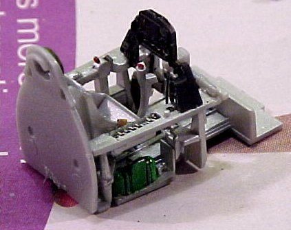
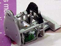 The
cockpit was assembled per the instructions. The kit provides you with
some options here: decal versus photo-etched seatbelt and rear-mounting
versus front-mounting decal instrument faces. I went with the decal on
the back side of the clear instrument panel after painting the front of
the panel flat black. Take care not to
The
cockpit was assembled per the instructions. The kit provides you with
some options here: decal versus photo-etched seatbelt and rear-mounting
versus front-mounting decal instrument faces. I went with the decal on
the back side of the clear instrument panel after painting the front of
the panel flat black. Take care not to 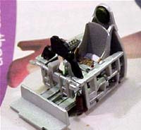 paint
over the instrument faces!
paint
over the instrument faces!
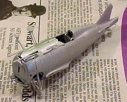
In Steps 2 and 3, the instructions suggest not gluing the interior into the fuselage halves until after the fuselage is assembled. Heed this advice. You must ensure that there are no leftover remains of the tree attachments in your subassemblies, as these will definitely mess up the fit and alignment of the subsequent steps. In any case, do dry-fit your parts together before applying cement. An early dry-fit of the interior revealed what would have been a source of frustration later on.
You may have heard some of the buzz about the fit of the gear doors in Step 4. While the instructions said they would fit perfectly, I did have to file the notches in each of the corners of the fuel tank sides to get the part to settle into place without popping off the fuselage underside. This was a one-minute challenge on each side of the aircraft, and they did indeed snap into place.
 The
main gear struts (C16/17) in Step 5 is the first good use of the cyano
tip. The top portion of the strut snaps into a ledge inside the fuselage
and this is a great spot for cyano reinforcement.
The
main gear struts (C16/17) in Step 5 is the first good use of the cyano
tip. The top portion of the strut snaps into a ledge inside the fuselage
and this is a great spot for cyano reinforcement.
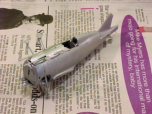
The upper fuselage deck (Part 52) is going to reveal whether the cockpit interior is properly installed. I found that I had not completely glued the fuselage halves to the fuel tank bulkhead, resulting in a poor fit of the upper fuselage deck. This was quickly and easily remedied again with cyano. I neglected to remove the tips of the machine guns until a later step (I got ahead of myself) but you'll find it easier to deal with the proper gun lengths before installing the upper fuselage deck.
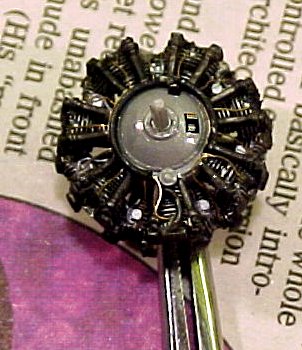
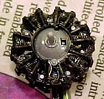 The
engine assembly is very nicely done (Step 7) with a photo-etched brass
part representing the ignition wiring.
The
engine assembly is very nicely done (Step 7) with a photo-etched brass
part representing the ignition wiring.
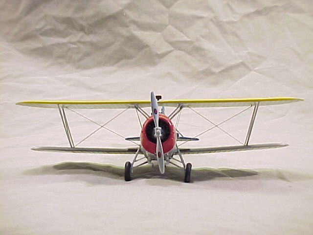
Before starting Step 8, this is the point at which you should decide on your aircraft markings. To do so later will only create potential frustrations. The USN in the 1930s used an interesting series of colored bands, chevrons, and cowl colors to signify the aircraft's place in the squadron/section. A different set of colors on the tail identified which aircraft carrier the squadron was assigned aboard. Refer to the tables at the end of this article for more information.
 What
Accurate Miniatures provides you with are decals to do essentially every
F3F-1 that ever flew. The decal sheet includes squadron badges, aircraft
bureau numbers, identification numbers, etc. It also provides you with
an ample supply of white and black border stripes to outline your fuselage
band, wing chevron and cowl band. However, you must paint the bands yourself.
The diagram in Step 16 lays out the band placements very nicely.
What
Accurate Miniatures provides you with are decals to do essentially every
F3F-1 that ever flew. The decal sheet includes squadron badges, aircraft
bureau numbers, identification numbers, etc. It also provides you with
an ample supply of white and black border stripes to outline your fuselage
band, wing chevron and cowl band. However, you must paint the bands yourself.
The diagram in Step 16 lays out the band placements very nicely.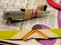
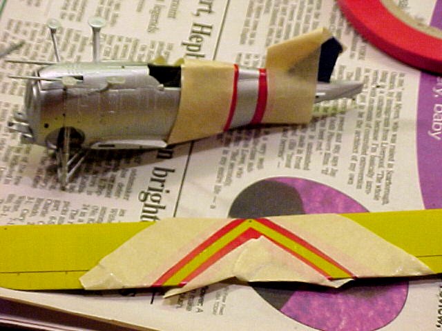
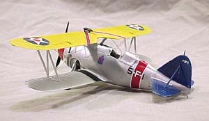
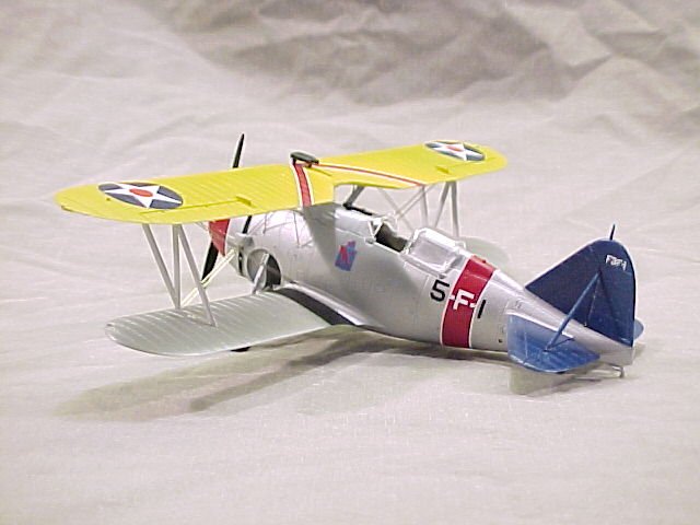
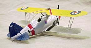
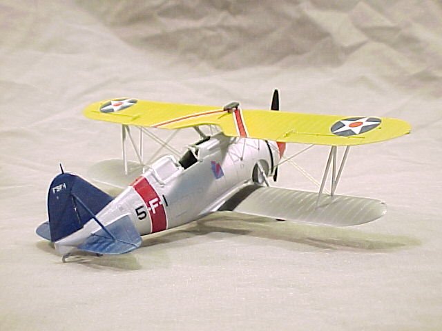
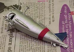
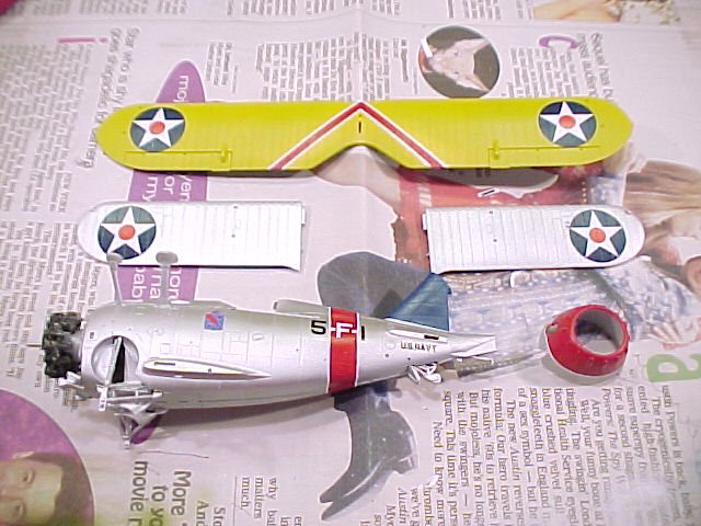
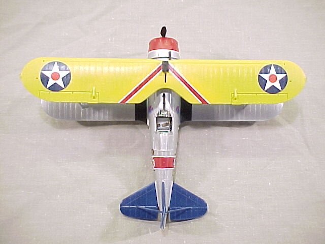
In order to get the markings done, I removed the upper wing, masked the lower surface and shot the topside and leading edge underside in Trainer Yellow.
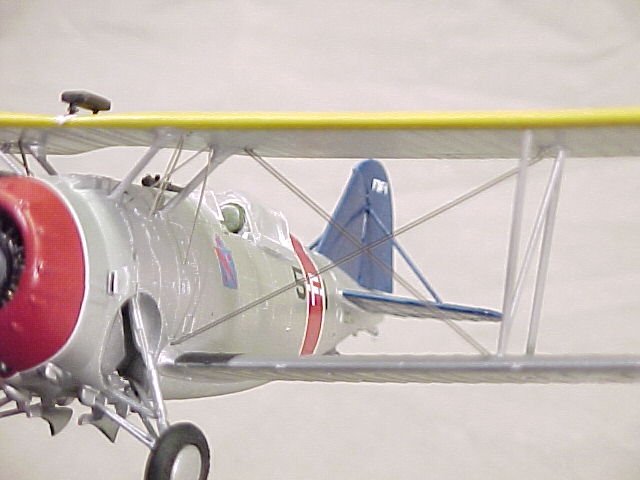
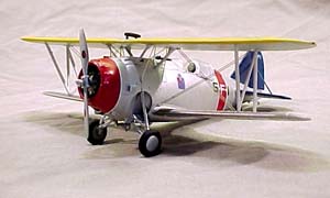
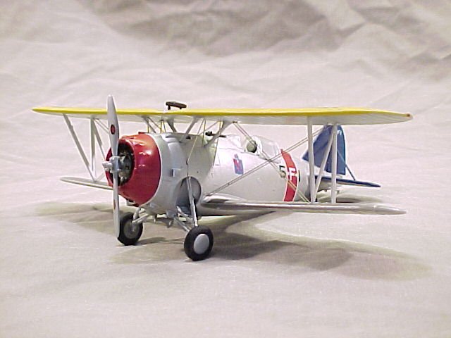
I decided to do the Squadron Commanders aircraft from VF-5B assigned to the USS Ranger in early 1937. The tail feathers were True Blue until July 1937, when VF-5B became VF-4 and the Ranger's colors were changed to Willow Green. I masked the vertical stab and painted the vertical and horizontal stabs, as well as the support struts, Tamiya Blue. Next, I masked and painted the cowl, upper wing chevron and fuselage band Tamiya Red.
After the identification colors dried, I applied the decals per Step
16. The decals required no setting solution to snuggle down onto the surface.
There was no hint of silvering or conformity problems. These are very
nicely done decals! A shot of Future on the wings 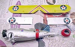 and
Gunze Sangyo Clear Flat on the fuselage sealed everything into place.
and
Gunze Sangyo Clear Flat on the fuselage sealed everything into place.
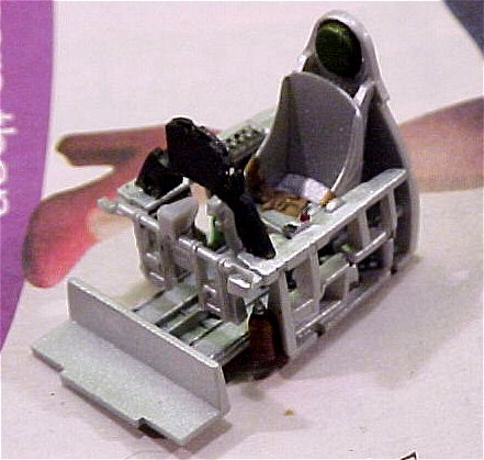
The ring and bead gunsight in Step 8 is an interesting combination of plastic and photo-etched steel. I must admit, I was skeptical that the 'handles' for the sights would twist off as advertised without yanking the parts themselves as well. I assembled them per the instructions and presto(!) they worked perfectly.
You have your choice of round or flattened wheels in Step 10. The instructions say to glue the brake housing (Parts C24) into place before adding the wheel and wheel cover. This is fine, but install the wheel and wheel cover while the glue is still wet so you can adjust the alignment of the wheel assembly. The wheel cover has a pin that runs through the wheel and brake assembly before mounting into a hole on the main gear strut. If the brake housing is not properly aligned, this could pose a problem.
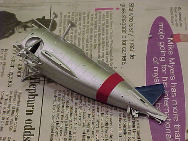
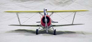
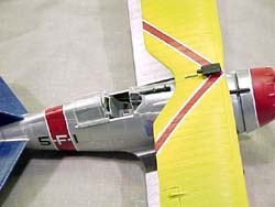 It
is now time to install the wings. Please ensure that the pads on the top
of the cabane struts are filed flat and smooth. If all is well, they will
literally snap into place in the upper wing. I used a touch of cyano on
all four pads to secure the upper wing in place. The lower wings fit equally
smooth. You'll need to carefully dry-fit the inter-wing N struts before
going any further. With the N struts adjusted, the lower wings go into
place with ease.
It
is now time to install the wings. Please ensure that the pads on the top
of the cabane struts are filed flat and smooth. If all is well, they will
literally snap into place in the upper wing. I used a touch of cyano on
all four pads to secure the upper wing in place. The lower wings fit equally
smooth. You'll need to carefully dry-fit the inter-wing N struts before
going any further. With the N struts adjusted, the lower wings go into
place with ease.

Step 14 is where we add the final details. I used white glue to install the windscreen. Everything goes together per the instructions.
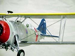 Now
we are faced with this new rigging scheme. The rigging is done from etched
steel, which is much more tolerant to being man-handled than brass. The
wide double flying wires (Parts PE90) snapped into their slots as advertised.
The narrow double flying wires (Parts PE91) were just a hair too short,
but this is where that cyano applicator came in handy. The cabane wires
(Parts PE92) were the most interesting part. If you look at the main rigging
diagram, it appears that they get twisted around in a peculiar way. Ignore
that diagram! Look at the diagram in the lower right corner of the page
ñ THAT is how the cabane wires are bent. I applied about a 30-degree bend
and then dry fit the cabane wires into place. They literally snapped into
place so well, I didn't dare remove them again. With a touch of cyano
again, the rigging is complete.
Now
we are faced with this new rigging scheme. The rigging is done from etched
steel, which is much more tolerant to being man-handled than brass. The
wide double flying wires (Parts PE90) snapped into their slots as advertised.
The narrow double flying wires (Parts PE91) were just a hair too short,
but this is where that cyano applicator came in handy. The cabane wires
(Parts PE92) were the most interesting part. If you look at the main rigging
diagram, it appears that they get twisted around in a peculiar way. Ignore
that diagram! Look at the diagram in the lower right corner of the page
ñ THAT is how the cabane wires are bent. I applied about a 30-degree bend
and then dry fit the cabane wires into place. They literally snapped into
place so well, I didn't dare remove them again. With a touch of cyano
again, the rigging is complete.
Summary
 This
was a fun project to undertake. I've avoided World War One subjects in
the past because of the hassles associated with rigging. This method that
Accurate Miniatures has devised makes short work out of the task! In addition,
the overall kit is nicely crafted. I did not need any filler in the construction
of this kit. Cyano was applied at stress mounting points, but not as a
seam filler.
This
was a fun project to undertake. I've avoided World War One subjects in
the past because of the hassles associated with rigging. This method that
Accurate Miniatures has devised makes short work out of the task! In addition,
the overall kit is nicely crafted. I did not need any filler in the construction
of this kit. Cyano was applied at stress mounting points, but not as a
seam filler.
If you're looking for something fun and different to build, and you like a lot of color in a small airframe, this F3F kit is just what you're looking for! I highly recommend this kit to any modeler.
Navy Colors in the F3F Era:
The Good News is that Accurate Miniatures provides beautiful squadron and identification markings to do virtually every aircraft in every applicable USN and USMC unit. The Bad News is that Accurate Miniatures is in the kit business, not the color and marking business. The research is up to you. The Good News is that Ill give you a head start. I put together a summary of colors/identifications from the references listed at the end of this article.
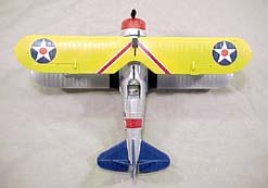 Each
squadron was divided into six sections, each section having three aircraft
apiece. Each section was assigned its own color. That color was in the
fuselage band, the cowl colors and the upper wing chevron. The entire
cowl and fuselage bands are in color for the respective section leaders.
The top half of the cowl received the color for the second aircraft in
the section, and only the bottom half in color for the third aircraft.
Note that while all three members of the section had the overwing chevron,
only the section leaders had the fuselage band.
Each
squadron was divided into six sections, each section having three aircraft
apiece. Each section was assigned its own color. That color was in the
fuselage band, the cowl colors and the upper wing chevron. The entire
cowl and fuselage bands are in color for the respective section leaders.
The top half of the cowl received the color for the second aircraft in
the section, and only the bottom half in color for the third aircraft.
Note that while all three members of the section had the overwing chevron,
only the section leaders had the fuselage band.
Across the side of the fuselage, centered on the colored band, is the unit and aircraft number. The first digit is the Squadron, the second is the Unit Type, and the third is the Aircraft Number. Therefore 4-F-1 is an aircraft from VF-4, which is a Fighter Squadron, and is the lead aircraft from the first section (Squadron Commander). 1-F-4 on the other hand is a VF-1B aircraft, also a fighter squadron, and is the first aircraft in the second section (aircraft number 4).
In the 1930s, squadron numbers were changed around all-too-often, so you'll need to do some homework as to which unit shield belongs to which squadron at any given time. To make life a little easier though, here is a complete squadron breakdown:
Aircraft Number | Section | Section | Color | Cowl | Example |
| | |||||
1 | 1 | 1 | Red | Entire | 4-F-1 |
2 | 1 | 2 | Red | Top | 4-F-2 |
3 | 1 | 3 | Red | Bottom | 4-F-3 |
4 | 2 | 1 | White | Entire | 4-F-4 |
5 | 2 | 2 | White | Top | 4-F-5 |
6 | 2 | 3 | White | Bottom | 4-F-6 |
7 | 3 | 1 | Blue | Entire | 4-F-7 |
8 | 3 | 2 | Blue | Top | 4-F-8 |
9 | 3 | 3 | Blue | Bottom | 4-F-9 |
10 | 4 | 1 | Black | Entire | 4-F-10 |
11 | 4 | 2 | Black | Top | 4-F-11 |
12 | 4 | 3 | Black | Bottom | 4-F-12 |
13 | 5 | 1 | Green | Entire | 4-F-13 |
14 | 5 | 2 | Green | Top | 4-F-14 |
15 | 5 | 3 | Green | Bottom | 4-F-15 |
16 | 6 | 1 | Yellow | Entire | 4-F-16 |
17 | 6 | 2 | Yellow | Top | 4-F-17 |
18 | 6 | 3 | Yellow | Bottom | 4-F-18 |
As I said earlier, during the period of operations of the F3F, the tail colors indicated to which carrier the squadron was assigned. Here are the carrier color assignments:
 1936-1937:
USS Langley – INSIGNIA RED
USS Saratoga – WHITE
USS Ranger – WILLOW GREEN
USS Lexington – LEMON YELLOW
USS Ranger – TRUE BLUE
After 1937:
USS Yorktown – INSIGNIA RED
USS Saratoga – WHITE
USS Ranger – WILLOW GREEN
USS Lexington – LEMON YELLOW
USS Enterprise – TRUE BLUE
USS Wasp – BLACK
My sincere thanks to Accurate Miniatures for this review sample!
References:
-
Color Schemes and Markings US Navy Aircraft 1911 – 1950, Bill C. Kilgrain, 1983 (Third Edition), Meridian Printing Ltd.
-
The Official Monogram US Navy & Marine Corps Aircraft Color Guide Vol 1 ñ 1911-1939, John M. Elliott, 1987, Monogram Aviation Publications


Previous: Contents

