


 DML
DRAGON'S 1/9TH SCALE
DML
DRAGON'S 1/9TH SCALE
Sd.Kfz. 2 KLIENES KETTENKRAD
KIT NO. 1804
By Larry Martinson IPMS/USA
Introduction
The old Esci 1/9th scale Kettenkrad has been hibernating for many years now. It finally has surfaced in a huge DML Dragon box. I've wanted one of theses kits for a long time. I was glad when I was given the opportunity to do a review on it.
 Upon
opening the box, I was astounded by the size of the kit (1/9th scale),
the number of parts (over 300), and the individual track links. It is
hard to believe that this kit is over 20 years old. The detail that it
has is a credit to ESCI. DML added a vinyl figure to the kit - which I
didn't use.
Upon
opening the box, I was astounded by the size of the kit (1/9th scale),
the number of parts (over 300), and the individual track links. It is
hard to believe that this kit is over 20 years old. The detail that it
has is a credit to ESCI. DML added a vinyl figure to the kit - which I
didn't use.
Upon closer scrutiny, I noticed that most of the large body parts were warped and the molds didn't line up very well. There is a nice amount of flash to clean up, which meant that the molds are kind of worn out. The instructions get a little busy, but if you take your time it's not too bad.
I highlighted the English in the instructions since they are multilingual. This will help you, so you're not spending so much time looking for the right words. I'm not sure what the letters stand for behind the part numbers in the instructions and there is absolutely no painting instructions in the kit.
STEP 1 & 2:
Are pretty easy. You install the wire springs on the torsion bar arms. *Take note: There are left and right handed springs. Be careful how much glue you apply to these torsion arms.
STEP 3:
 Here
things get busy. You start putting the main body together, which consists
of two sides, a bottom, and a front. Take your time when cleaning up these
parts and glueing. My parts were warped and the fit required a bit of
filling and sanding. DML wants you to mount the sprockets and bogies,
but I left them off for ease of painting later. The loops, which hold
the axe on the side panel, are mislabeled as #261, they should be #216.
Here
things get busy. You start putting the main body together, which consists
of two sides, a bottom, and a front. Take your time when cleaning up these
parts and glueing. My parts were warped and the fit required a bit of
filling and sanding. DML wants you to mount the sprockets and bogies,
but I left them off for ease of painting later. The loops, which hold
the axe on the side panel, are mislabeled as #261, they should be #216.

STEP 4:
In this step, the sponsons (fuel and tool box) assemblies are tackled. Be very careful when applying glue to the hinges on the doors. They are supposed to open. On the inside of the doors (parts #152 & 167) are some large push-out pin marks that have to be sanded off. You will need some wire to extend the battery cables. I didn't glue the sponsons in yet - for ease of painting later - again.
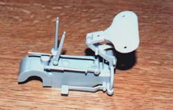
STEP 5:
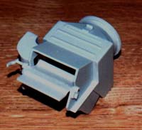
Here you put the bell housing together. It consists of three parts and that's all you do.
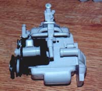
STEP 6:
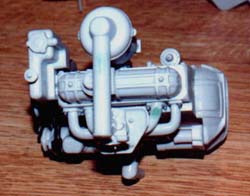 Unless
you're a gearhead, or just plain engine orientated, this step is both
DIFFICULT and CONFUSING! The instructions are so busy, with arrows and
numbers, that it is hard to tell what's what and where it goes. It should
have been made into two (or more) separate steps. Take your time with
this step. There is a lot of sanding and dry fitting of parts to be done,
with the intake and exhaust manifolds. They also need Grant Line nuts
and washers added, so they look attached to the head. The pulley and belt
system is a NIGHTMARE of dry fits and trying to get the configuration
right! I still don't know if I'm right, but the way I have it seems the
most logical.
Unless
you're a gearhead, or just plain engine orientated, this step is both
DIFFICULT and CONFUSING! The instructions are so busy, with arrows and
numbers, that it is hard to tell what's what and where it goes. It should
have been made into two (or more) separate steps. Take your time with
this step. There is a lot of sanding and dry fitting of parts to be done,
with the intake and exhaust manifolds. They also need Grant Line nuts
and washers added, so they look attached to the head. The pulley and belt
system is a NIGHTMARE of dry fits and trying to get the configuration
right! I still don't know if I'm right, but the way I have it seems the
most logical.
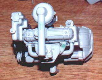
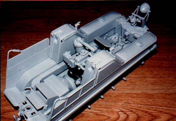
Don't install the engine yet, it will be easier to paint the vehicle's insides without it in there yet, and easier to paint the engine too. I painted the engine black and the carburetor brass aluminum.
STEP 7:
 This
step was a treat after step #6. You assemble the oil bath breather, distributor,
and coil. Then you put them on the engine. The spark plugs are put in,
along with the spark plug wires. I opted to leave the wires off, until
I had the engine painted.
This
step was a treat after step #6. You assemble the oil bath breather, distributor,
and coil. Then you put them on the engine. The spark plugs are put in,
along with the spark plug wires. I opted to leave the wires off, until
I had the engine painted.

STEP 8:
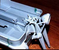
Here you attach shifting levers for the gearbox/transmission. Part of the rider's seat suspension and the left hand steering brake are also covered. The black rubber knobs, that go on the shifting levers, I left off until after the base color was applied. Part #174 needed some trimming, to make it stand upright. Be sure part #114 does not poke through the eyelets on part #82. Let this step dry overnight before going any further.
STEP 9:
 In
this step you continue to install seat suspension parts: the right hand
steering brake, emergency brake handle, and the seat. On parts #178 &
179 I needed to enlarge the holes a little where they slide into parts
#175 & 176. Glue #178 & 179 to #177 (the bottom of the seat) and let dry
overnight before you force them onto #175 & 176. Paint this assembly before
installing it into the main body.
In
this step you continue to install seat suspension parts: the right hand
steering brake, emergency brake handle, and the seat. On parts #178 &
179 I needed to enlarge the holes a little where they slide into parts
#175 & 176. Glue #178 & 179 to #177 (the bottom of the seat) and let dry
overnight before you force them onto #175 & 176. Paint this assembly before
installing it into the main body.

STEP 10:
 This
step covers the construction of the box-like radiator housing. The large
cooling flap DOES WORK, if you are careful with the glue. Later, I found
out you need to make a radiator that will fit inside. There is two vertical
edges that you can glue it to on the inside - install it from the flap
side.
This
step covers the construction of the box-like radiator housing. The large
cooling flap DOES WORK, if you are careful with the glue. Later, I found
out you need to make a radiator that will fit inside. There is two vertical
edges that you can glue it to on the inside - install it from the flap
side.

STEP 11:
This step is a little tricky, with the fitting of parts #162, 166, 204, 206, and 207. This will end up being the driver's dash and cooling vents on the floor for the steering clutches. I chose not to put the gauge decals on until after painting.
After step 11, I felt it was time to paint the sub-assemblies, the inside of the vehicle, and the storage sponsons (from step 4). Then I installed them all accordingly now.
STEP 12:
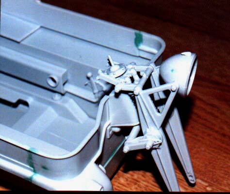
Here is where all the sub-assemblies come together, and you start to feel like you're getting somewhere. You can do the engine wiring, that's called for, but I decided to go further and do the generator, regulator, starter, and other accessories also.
STEP 13:
 In
this step you work on the tricycle front end. There is a lot of moving
parts on the fork, so be careful when applying the glue. I didn't put
the headlight lens, or lens retainer ring on, due to the way I was painting
the vehicle. I will install it at the very end of the assembly. Be extremely
careful when putting the black tubing on, which represents the headlight
wiring. You can break the plastic posts which the tubing fits onto very
easily.
In
this step you work on the tricycle front end. There is a lot of moving
parts on the fork, so be careful when applying the glue. I didn't put
the headlight lens, or lens retainer ring on, due to the way I was painting
the vehicle. I will install it at the very end of the assembly. Be extremely
careful when putting the black tubing on, which represents the headlight
wiring. You can break the plastic posts which the tubing fits onto very
easily.
STEP 14:
Now you attach the fork to the main body. Use extreme care when doing this, and also with the black tubing attachment points again - they are very fragile!
STEP 15:
 This
step involves the assembly of the fender, notek light, and handle bars
for the fork. I didn't put the front wheel on yet - again for ease of
painting.
This
step involves the assembly of the fender, notek light, and handle bars
for the fork. I didn't put the front wheel on yet - again for ease of
painting.
I thought the headlight tubing was kind of hairy to do. Putting the tubing on the handlebars is worse yet - so WATCH OUT!! You can break off the attachment points - as I have already warned!
STEP 16:
In this step you put the rear light and license plate holder together. There is a flap that opens and closes (part #230). I believe this allows cold air in for the radiator inlet. On the back of part #208 it's left open. I didn't think this was right, so I enclosed it with a piece of flat styrene card. Don't glue this assembly down, later on you will find they provide hinging tie downs for it.
STEP 17:
The rear seat is put together in this step. Under the seat is a storage area where you can put the tool set, which is provided in the kit. Part #3, in my kit, was severely warped! I was able to take some of the warp in it out, but not all of it!
Step 18:
The engine cover hood is put together now. You sandwich a piece of black mesh between the hood and the inside retainer frame, then you put the hinge on for the hood. I had to extend the fingers that fit into the side sponsons, otherwise it doesn't want to stay in place.
STEP 19:
 Here
I found that the engine hood doesn't want to set down the way it's intended!
It seems to be warped a little and the slots in the sponson are not deep
enough. I filed the slots a little deeper and did some sanding on the
hood (where the hinge hits when lowered down). Part #232 is a type of
hold down clamp for the license plate holder. Slip them on the pins, then
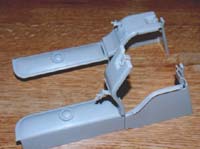
carefully apply glue to the nuts (part #67). Part #232 should move freely.
Set the license holder from step 16 on and swing part 232 around till
it latches down. Repeat this operation for the other side. Part #182 looks
like a toggle switch panel for light, starter, and other electrical needs.
I enclosed the sides, then drilled a hole in the right hand side for a
wire loom to enter into it. At this point, I painted the bogies and the
rest of the vehicle's insides and exterior. I then put the rim and tire
together and installed it on the fork system. I also installed all the
black vinyl seats, handle bar grips, and shift lever knobs. The personal
gear was left off until later because I'm going to include some gear from
DML's 1/9th scale Zundapp motorcycle kit.
Here
I found that the engine hood doesn't want to set down the way it's intended!
It seems to be warped a little and the slots in the sponson are not deep
enough. I filed the slots a little deeper and did some sanding on the
hood (where the hinge hits when lowered down). Part #232 is a type of
hold down clamp for the license plate holder. Slip them on the pins, then
carefully apply glue to the nuts (part #67). Part #232 should move freely.
Set the license holder from step 16 on and swing part 232 around till
it latches down. Repeat this operation for the other side. Part #182 looks
like a toggle switch panel for light, starter, and other electrical needs.
I enclosed the sides, then drilled a hole in the right hand side for a
wire loom to enter into it. At this point, I painted the bogies and the
rest of the vehicle's insides and exterior. I then put the rim and tire
together and installed it on the fork system. I also installed all the
black vinyl seats, handle bar grips, and shift lever knobs. The personal
gear was left off until later because I'm going to include some gear from
DML's 1/9th scale Zundapp motorcycle kit.

STEP 20:
 With
this last step, you assemble the tracks, mud flaps, and exhaust muffler.
The instructions also show where to put decal markings now. I put the
markings on my vehicle and used a division marking from the DML Zundapp
kit. It represents the100th Panzer Brigade. The tracks took me 1 1/2 hours
to clip off the trees - and eight more hours of cleaning up and assembling
them. I then painted the tracks. Then I installed the axe and shovel on
the sides of the vehicle. After a couple days, I dull-coated the Kettenkrad
and put all the lenses for headlight and gauges in. From this point on
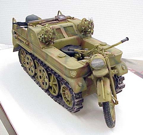
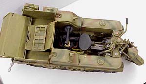
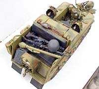
I worked on the numerous extra personnel gear and I applied a 3-color
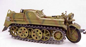
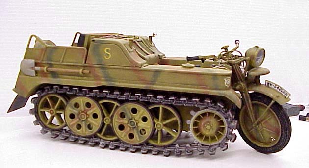
camouflage scheme that was used by the Wehrmacht late in the war.
With
this last step, you assemble the tracks, mud flaps, and exhaust muffler.
The instructions also show where to put decal markings now. I put the
markings on my vehicle and used a division marking from the DML Zundapp
kit. It represents the100th Panzer Brigade. The tracks took me 1 1/2 hours
to clip off the trees - and eight more hours of cleaning up and assembling
them. I then painted the tracks. Then I installed the axe and shovel on
the sides of the vehicle. After a couple days, I dull-coated the Kettenkrad
and put all the lenses for headlight and gauges in. From this point on
I worked on the numerous extra personnel gear and I applied a 3-color
camouflage scheme that was used by the Wehrmacht late in the war.

CONCLUSION
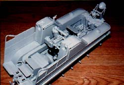
This is the LARGEST project I have ever tackled! Despite some of its pitfalls, the kit really makes up into a eye-stopper! The main problem with the kit was the warpage, which I think DML could have avoided.
The kit's strong points are the working suspension, working doors, hood, and other numerous details. It begs for more super details, due to its size!
I would recommend this kit to any experienced modeler, who likes small soft skinned vehicles - in a LARGE scale!
I would like to thank Greatmodels Shop for providing this kit and Ray Mehlberger for allowing me the opportunity to build and review it. It was an AWESOME experience!


Previous: Contents

