


 Czechmaster
Resin 1/72 Morane-Saulnier Type AI
Czechmaster
Resin 1/72 Morane-Saulnier Type AI
By Matt Bittner
Photography by Don Van Hook
History
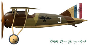
The Type AI was Morane-Saulniers (MoS) last attempt at a WW1 aircraft. It was developed in conjunction with a typical biplane fighter (the Type AF) but due to the excellent qualities of the Type AI, it was put into production instead of the Type AF.
Initially the Type AI passed all structural tests with flying colors in fact, using these tests as a guideline it was one of the strongest aircraft ever produced. The initial flight of the Type AI left the pilots enthusiastic, and at the time it was thought that the Type AI was the best aircraft flying at that point. There were three Escadrilles (squadrons) that were converted into the Type AI MSP 156, MSP 158 and MSP 161.
 There
were three sub-types of the Type AI produced. The MoS designation for
the single gunned example was MoS.27.C1, while the type with two Vickers
was known as the MoS.29.C1. The trainer version which used the 120hp
LeRhone instead of the Gnome engine found in the fighter version was
designated the MoS.30.E1.
There
were three sub-types of the Type AI produced. The MoS designation for
the single gunned example was MoS.27.C1, while the type with two Vickers
was known as the MoS.29.C1. The trainer version which used the 120hp
LeRhone instead of the Gnome engine found in the fighter version was
designated the MoS.30.E1.
Unfortunately it appears that during normal combat flying the AI proved to be quite deadly. Due to forces unknown back then (most likely wing flutter) the AI tended to shred its wing during combat. However, it appears this only happened a couple of times, but it was enough to convince the French to pull the type from front-line service, and relegate the type to training duties only.
Personally I feel it was a shame that Morane-Saulnier was not allowed to correct the errors. According to some of Walter Shaffers letters to home, the Type AI was extremely nimble in combat, and could out-perform anything in the sky at that time.
The Kit
The kit consists of approximately 45 resin pieces and a superb decal sheet that covers two aircraft Rufas Rands of MSP 158, and Walter Shaffers of MSP 156. However, Sgt. Shaffers machine was a MoS.27.C1 which was a single gun machine so out of the bag, this kit cant be used to build his machine. Unfortunately photos of MoS.27.C1 machines arent prevalent, especially in the area of the forward, upper fuselage, where the gun is. The MoS.29.C1 (and .30) had a hump like a Sopwith Camel where the guns were. It appears that MoS.27.C1s did not have this hump; instead the gun was mounted directly onto the forward, upper fuselage. Unfortunately thats all conjecture, as I have found no clear pictures showing this area.
 Construction
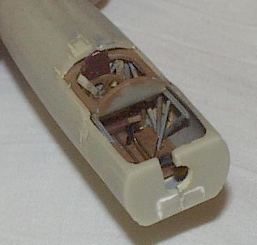
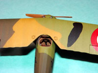
Naturally construction starts in the cockpit. Everything you need minus the fuel control, wires and seat belts are included in the kit. The cockpit is a work of art! In order to get everything lined up onto the floor, I decided to use a piece of balsa and pin the floor to it while gluing on the tubular sides. This worked great, and with the way the kits cockpit is designed, alignment is excellent. I added stringers to the sides of the cockpit, even though it is difficult to see some of them once the cockpit is closed. Colors in the cockpit were medium gray for the forward areas, natural wood for the instrument panel and pilot surround, and light gray for the metal areas of the tubular structure. The seat was painted a leather color, and the belts which came from the Tom Modelworks French set were painted a grayish-clear doped linen color.
Before gluing the fuselage halves together, I cut the rudder off the one-piece rudder/fin which is attached to one fuselage side. Once that was cut off and cleaned up, then the cockpit was glued into one fuselage side, and the fuselage halves were glued together. There is very little seam to clean up, and this area is better than most injected molded kits I have built. Another shining example of the excellent qualities of this model.
 Once
the seam was cleaned up with just a light sanding I started to work
on the cockpit enclosure piece. This required some dry fit and sanding
to get to fit correctly which included gluing the upper, cockpit tubular
structure direct to the cockpit sidewalls. After cutting the control surfaces
from the horizontal tailpieces, I glued the fixed stabilizers to the fuselage,
and started to prep for painting.
Once
the seam was cleaned up with just a light sanding I started to work
on the cockpit enclosure piece. This required some dry fit and sanding
to get to fit correctly which included gluing the upper, cockpit tubular
structure direct to the cockpit sidewalls. After cutting the control surfaces
from the horizontal tailpieces, I glued the fixed stabilizers to the fuselage,
and started to prep for painting.

Final Assembly and Painting
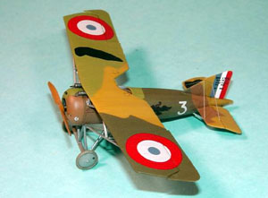
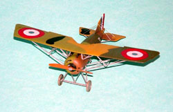
Using the kit instructions as guidelines photocopied and cut out
I started to paint. After spraying the underside aluminum, I masked it
off and sprayed the uppers beige (actually Polly Scales British Middlestone).
(Although the instructions say to paint the undersides yellow, according
to the Mini-Datafile there is official documentation that states the undersides
were finished in aluminum.) After the beige dried a couple of days, then
the rest of the colors were sprayed on, 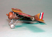 starting
with the light green (Polly Scales Germ. RLM 68 Lt. Ol. Gr.), followed
by the dark green (Polly Scales Fr. Fok. Dark Green) and the dark brown.
(Unfortunately I sprayed on the wrong brown on the model, but decided
to keep it since its pretty close. The Polly Scale color that is more
accurate is Ger. RLM 61 Dk. Brn.) All colors were thinned not only with
thinner, but also with Future. This meant a pretty decent gloss coat
for decal adhesion.
starting
with the light green (Polly Scales Germ. RLM 68 Lt. Ol. Gr.), followed
by the dark green (Polly Scales Fr. Fok. Dark Green) and the dark brown.
(Unfortunately I sprayed on the wrong brown on the model, but decided
to keep it since its pretty close. The Polly Scale color that is more
accurate is Ger. RLM 61 Dk. Brn.) All colors were thinned not only with
thinner, but also with Future. This meant a pretty decent gloss coat
for decal adhesion.

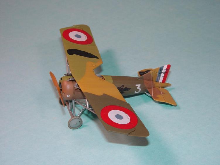
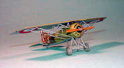
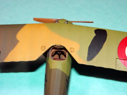
After waiting a couple of days for everything to dry, I added the decals. I wanted to model Sgt. Schaffers machine, but I already glued on the upper, forward fuselage before realizing that Schaffer flew the MoS.27.C1 instead of the MoS.29.C1 the kit represents. So I went with Rands machine instead. The decals are excellent, in perfect register and snuggled down nicely.
 Now
that the decals were on, and everything dry I started to add the wing.
This is the only time I have used a jig to help with wing placement and
alignment. Normally I make sure the lower wing is perfect, and use that
as my guide when I add the upper wing. Since the MoS Type AI was a high-wing
monoplane, I had no lower wing to guide from. After creating the jig from
balsa and cardboard, I was able to get everything lined up correctly and
started adding the multiple wing struts.
Now
that the decals were on, and everything dry I started to add the wing.
This is the only time I have used a jig to help with wing placement and
alignment. Normally I make sure the lower wing is perfect, and use that
as my guide when I add the upper wing. Since the MoS Type AI was a high-wing
monoplane, I had no lower wing to guide from. After creating the jig from
balsa and cardboard, I was able to get everything lined up correctly and
started adding the multiple wing struts.
Unfortunately the wing struts in my kit were completely unusable, so I substituted brass Strutz! for all wing struts. This was a little more of a pain than using Contrail plastic struts, but I wanted the strength the brass would give me. After gluing the longer, main struts to the wing and fuselage, I then removed the model from the jig, and added the rest of the struts. Quite time consuming since there is a large array of struts on the wing.
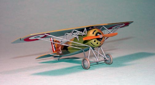
 Once
the wing struts were in place and dried for a few days I then finished
the model by rigging with .005 stainless steel wire, added the horizontal
tail struts and finally the landing gear. I gave the model a burnt sienna
oil wash and finished with an overcoat of PollyScale flat. The prop was
painted and a coat of Future gloss was applied then the prop was glued
to the engine.
Once
the wing struts were in place and dried for a few days I then finished
the model by rigging with .005 stainless steel wire, added the horizontal
tail struts and finally the landing gear. I gave the model a burnt sienna
oil wash and finished with an overcoat of PollyScale flat. The prop was
painted and a coat of Future gloss was applied then the prop was glued
to the engine.
The kit is engineered in an excellent way to allow the prop and engine to spin together, so I just had to build the model with the moving parts. I normally glue everything solid especially since most kits do not allow the prop and engine to turn simultaneously but with this kits engineering, making the prop and engine spin was easy.
Conclusion
This is the best WW1 kit I have ever built. With the inclusion of a complete cockpit (sans seat belts) as well as decals, it is also a complete kit. I can not recommend this kit highly enough. Buy plenty of them and convince Czechmaster to release more WW1 kits.
If youre listening, Czechmaster, we could do with the rest of the Morane-Saulniers, especially the Type AC and Type P.
References
Albatros Publications, Inc., Windsock Mini-Datafile #5, Morane-Saulnier Type AI
Windsock Magazine, Vol. 8, No. 3
Over the Front, Vol. 9, No. 1
My thanks to Czechmaster for supplying this superb kit.


Previous: Contents

