 A
Two-Seat Harrier in 1/24th Scale
A
Two-Seat Harrier in 1/24th Scale
By Frank Mitchell
The Goal
For no particular reason, the two-seat Harrier appeals to me. The single-seater has always appeared to be a bit short and squatty, but the extra length and tall tail of the two-seater makes all the difference.
Many years ago, I converted the Revell 32nd Harrier to a two-seater, but that model disappeared somewhere along the way (I think my dog had something to do with that), so when the 1/24th Harrier came out, the idea began to simmer again. I was also curious to see just how big the model would be in that scale.
The first step was to decide on what plans I would use. There are a fair number of three-views available, but I chose drawings that had appeared in Scale Models (the old British one) from many years ago. These were blown up to 24th scale and it became apparent that building the model would not be all that bad, but dealing with the sheer size of the thing would be interesting.
 Conversion
Beginnings
Conversion
Beginnings

The forward fuselage was first. The kit fuselage halves were taped together, and the nose was cut off at the rear base of the windscreen. A rough balsa mold was carved and sanded to the general shape of the fuselage, and two pieces of 40 thousandths styrene (one for each side of the fuselage) were shaped by the heat-and-smash technique, which consists of smashing a piece of heated plastic over a mold which is being held in a vice. The shape of the mold was determined by tracing the curve of the fuselage from the nose onto the end of a piece of scrap balsa. No real attempt was made smoothly finish this mold; I didn't really care if a little grain showed through.
In order to make sure that everything would line up and be straight,
one of the molded styrene pieces was cut to the proper length, squared
off, and glued between the pieces of one half of the fuselage. The second
piece was cut to the correct length, but before it was glued into place,
the two still-separate pieces of the other 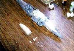 fuselage
half were securely taped to the glued side. The second piece was now glued
into position. When the tape was removed, both halves automatically matched
and fitted together correctly.
fuselage
half were securely taped to the glued side. The second piece was now glued
into position. When the tape was removed, both halves automatically matched
and fitted together correctly.

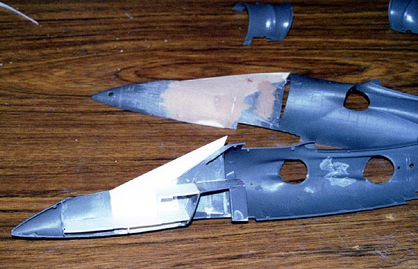
Next, two more pieces of 40 thousandths styrene were cut to form the sides of the cockpit and were glued into place. No mold was used for this step because there was very little or no compound curvature needed. Two-part epoxy putty was used to fair in these pieces and the fuselage extension. The epoxy is a wood-color in the photos.
Before the fuselage halves could be joined, the interior of the fuselage needed some work.
The Interior
 The
engine was assembled according to the Airfix plans. The face of the compressor
was detailed and painted, and the four engine nozzles modified so that
they could be attached after all exterior painting was complete.
The
engine was assembled according to the Airfix plans. The face of the compressor
was detailed and painted, and the four engine nozzles modified so that
they could be attached after all exterior painting was complete.
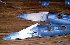
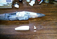
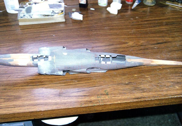
A new floor for the forward cockpit was cut from .040 styrene using the stock floor as a guide for the width. To this was added a new raised floor for the rear cockpit and the floor of the rear cockpit was integrated with some of the kit parts to form the nosewheel well. None of this was all that difficult, just some attention to correct measurements and trying to be accurate while cutting the plastic (Photo 1). The fuselage halves were glued together, trapping the engine between them.
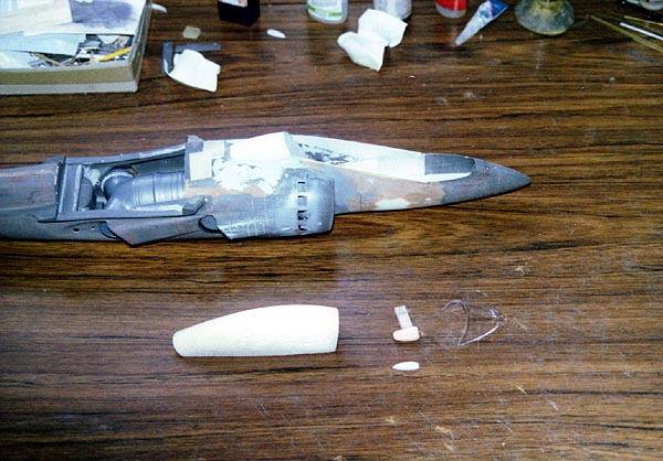
A piece of balsa was shaped to form a mold for the fairing at the rear
of the cockpit. This was done by tracing the side-view outline of the
piece on to the balsa. The width was taken from the rear of the cockpit
sides. The piece was carved and sanded to 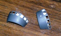 shape,
taking into account the thickness of the plastic from which the fairing
would be molded by heat and smash. The fairing was trimmed to shape and
glued in place.
shape,
taking into account the thickness of the plastic from which the fairing
would be molded by heat and smash. The fairing was trimmed to shape and
glued in place.
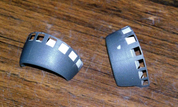
While still at the front of the fuselage, I corrected one of the problem areas of the kit: the bypass doors in the intakes. The correction was tedious, but not all that difficult. The correction involved carefully cutting out all the door openings in the kit parts, cutting new doors from .020 styrene, and fitting the new doors in place at the proper angles from inside the intakes using scrap pieces of plastic.
 The
New Canopy
The
New Canopy
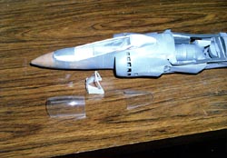
A mold for the canopy was made by first taping the windscreen in place and then cutting a block of balsa to fit between the inside the windscreen frame and the rear cockpit fairing. When that was accomplished, the remainder of the canopy was carved and sanded to shape using a long sharp blade and sandpaper. Allowance was again made for the thickness of the plastic that would be used to make the canopy. A small mold was also prepared for the two intake scoops that are mounted on the rear canopy fairing.
Since the clear parts needed to be as clear and free of surface defects as possible, the canopy mold was covered with epoxy, then sanded and polished. The canopies were formed from 1/32nd clear plexiglass using heat-and-smash.
Another "canopy" was molded from .030 white styrene. After the clear
canopy was cut into front and rear portions, the styrene molds were placed
inside the clear portions and the outlines of the clear parts were traced
onto the white. The portions 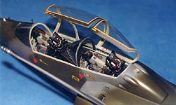 of
the canopy that are clear were cut from the white molds to produce frames
for the interior of the canopy. These formed frames that were scale thickness
and also allowed easier detailing than would the clear parts. The interior
frames were also painted before being glued in place because they would
be very difficult to mask inside the canopy. Canopy hinges were made from
brass wire.
of
the canopy that are clear were cut from the white molds to produce frames
for the interior of the canopy. These formed frames that were scale thickness
and also allowed easier detailing than would the clear parts. The interior
frames were also painted before being glued in place because they would
be very difficult to mask inside the canopy. Canopy hinges were made from
brass wire.
The cockpit interior was begun by building the rear cockpit windscreen and its attendant support. This involved yet another mold, again using the drawings for the shape, but making sure that it would fit the opening correctly.
Instrument panels and consoles were made (using balsa for the consoles) in the normal manner. All interior panels and controls had to be scratchbuilt since that weren't (and still aren't) any aftermarket accessories for 24th scale aircraft. Both ejection seats were also scratchbuilt because I felt that it would actually be easier than trying to match the kit part (which, in any case, needed considerably more detailing).
 Tail
Changes
Tail
Changes
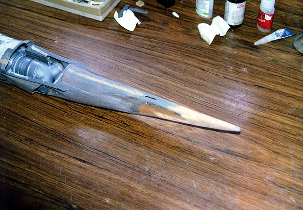
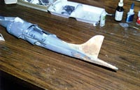
The modifications to the rear of the fuselage tail were actually fairly easy. The horizontal tail is mounted in the same place as the single-seater; the added length being behind the stabilizer. The fuselage was therefore cut off just behind the mounting points for the stabilizer, and the added portion was carved from pine. This was glued into place and the new portion was faired into the fuselage with epoxy.
A new vertical tail was formed from balsa. Once the shape was finished,
the balsa was soaked with thin superglue which greatly strengthens and
stabilizes the wood. This  was
then sanded and covered with putty to cover the grain. The rudder was
cut from the fin and provisions made to re-attach the rudder with brass
wire.
was
then sanded and covered with putty to cover the grain. The rudder was
cut from the fin and provisions made to re-attach the rudder with brass
wire.
From this point on, the rest of the aircraft was built according to the kit directions. The only other modifications were putting down the flaps, and detailing where necessary.
Finishing Touches
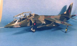
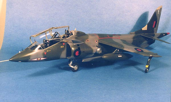
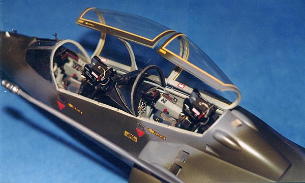
When the construction was complete, there was a good deal of the dreaded filling, priming, and sanding until I was happy with the surface. The paints were Gunze dark sea gray and dark green. The roundels were painted on using circles cut from frisket paper, and the various red outlines masked off with narrow pieces of drafting tape (this looks like masking tape, but is much less aggressive and thus less likely to pull off paint or coatings).
 The
squadron markings came from the kit and various other small markings came
from the spares box. The finished model was overcoated with Floquil Crystal
Cote which I think gives a nice finish for modern jets.
The
squadron markings came from the kit and various other small markings came
from the spares box. The finished model was overcoated with Floquil Crystal
Cote which I think gives a nice finish for modern jets.

This was actually a fun model to build, and was really rather straightforward. The biggest problem was the size, which was both a blessing and a curse. Easier to make parts, but lots more details have to be added because they can all be seen. On the other hand, the model isn't easily overlooked. In retrospect, if I were doing this model again, I think I would opt for one of the display schemes; much prettier.


