Vickers-Clyno 'Mk' III (Part 1)By Karen Rychlewski | 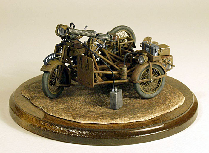 |
Overview
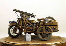
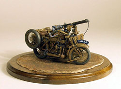
On 22 October 1915 the British Army formed the Machine Gun Corps to support infantry and cavalry units. One arm of the M.G.C. was called the Motor Machine Gun Corps and it was to be equipped with motorcycle mounted machine guns. After the usual trials, the Clyno firm was selected to produce these motorcycle-sidecar combinations. The Clyno was quite advanced for its time: it had a 5-6 hp 3-speed V-twin engine which was easily removable, a fully enclosed final chain drive, spring forks on the front wheel, three-point leaf suspension on the sidecar, and interchangeable wheels.
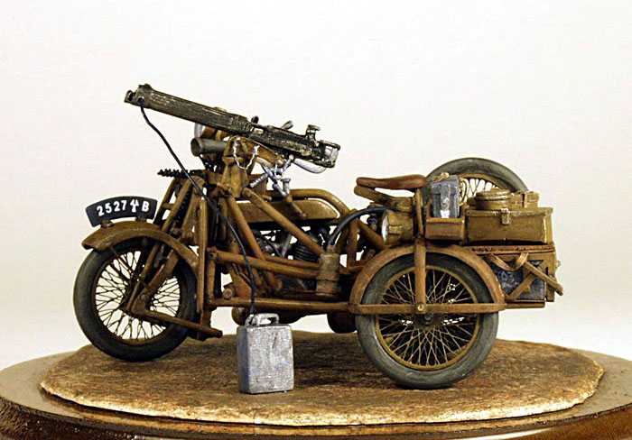
 The machine gun and its shield were mounted to the sidecar on the usual tripod mount, thus the gun could be fired forward by the passenger or it could be removed completely for normal ground use. It could also be mounted to fire to the rear. Behind the passenger seat was stowage for ammunition, water (for the gun-cooling system), spare petrol, oil, gun parts, and carbide for the two headlamps.
Three of these vehicles comprised a single gun unit: one carried the gun, a second was modified to carry a load of ammunition instead of a passenger, and the third was a spare. On formation, the M.M.G.C. was equipped with four batteries of Clynos and about 1800 were eventually built. The speed and mobility of the Vickers-Clyno machines enabled them to serve on every front of the war in virtually any weather. Appropriately enough, it was the Machine Gun Corps which later manned the first British tanks in 1916 and from which the Tank Corps later grew.
 The Kit
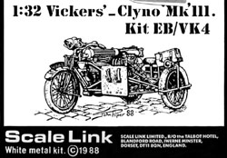
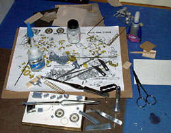
The kit of this important early military vehicle is produced by Scale Link, Ltd, of Dorset, England. It is a 1/32 scale kit (Kit EB/VK4) comprised of 82 cast metal parts, one fret of photo-etched wheel spokes and the ammunition carrier, and a sheet of number plate decals with 4 choices; the machine gun (available separately as Kit EB1) has 12 metal parts and a photo-etched ammo belt, leaf back sight, and elevating wheel. All but the tiniest parts are loose and packed in plastic bags roughly corresponding to the different sub-units of the model. The metal parts are nicely detailed and well cast with only minimal flash which nevertheless takes quite a bit of time and care to remove; some parts are so small that they can only reasonably be cleaned up after attaching them to other parts. Your smallest files and Dremel bits will come in handy with this model.
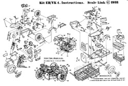 There are very few locating holes and pins for assembly and in fact, several holes have to be drilled to accept the pins on some parts. As described below, this caused many problems with fit and glue adhesion. Three pages of instructions include a parts list, an 'exploded' drawing, and an 'assembly guide' (my kit arrived from England without the instructions and a frantic email to Scale Link produced them in about 5 days). This is definitely NOT a kit for a beginner, and even the advanced modeler, if his experience has been confined to plastic kits, will find the assembly, as they say, 'challenging'.

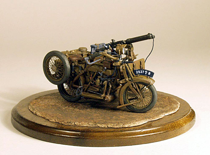
 The accuracy of the model was difficult to judge because I was unable to find good photographs or detailed drawings of the original. Some research of 1914-era motorcycles helped to clarify the purpose of all the pieces and parts, and also to identify items that were missing from the kit. In general, the parts seem accurate to this motorcycle brand but the casting of many parts seems overly thick. The two biggest flaws involve the tires and the wires: the tires are entirely without tread--since I doubt the British Army would run 'slicks' on motorcycles, this is a disappointing flaw which is ultimately very obvious. The wires also are entirely missing: like a biplane without rigging, a motorcycle without wires and cables looks naked--much research and assistance from the knowledgeable members of the WWI Modeling email list resulted in my adding wires and such at what seem the appropriate places. Since Scale Link must have had access to a real vehicle or drawings of one, it seems to me they could include a wiring diagram for those of us who want to further detail the model.

The Build
The kit can be built as either the machine gun carrier or the ammunition carrier; I chose to build the machine gun version because my ultimate goal is to use the model in a small diorama. I quickly deviated from the 'assembly guide' and built the model in several sub-units which were finally assembled only at the very end. Quick-setting epoxy and 'Super Glue' are the only choices for sticking parts together; the instructions caution against trying to use solder but I suspect an expert at the technique (which I am not) would find this more durable than glue.
 Wheels
Each of the four tires is cast as a single piece, with narrow ledges for the placement of the PE spokes. As noted, the tires have no tread--after much meditation, I decided to leave them that way. Trying to 'carve' tread into double curved metal surfaces is not my idea of fun; I didn't like the way they looked, but I thought that with enough mud, maybe the 'slicks' wouldn't be so visible.
Since I'm used to building PE wire wheels from my biplane modeling, I figured these wouldn't be much different--wrong again! Scale Link uses a rather unique system for fitting the spokes: each wire spoke piece has eight tiny notches around its edge and at first I thought one was supposed to fold them slightly at these notches. Then I realized that one was to CUT the edge at each notch, resulting in spokes divided like an eight-piece pizza and attached at the center. Aha, I thought, just the thing to allow for the 'bulge' of a real spoked wheel when the hub was inserted; and had everything gone well, that's what should have happened.
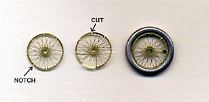 The first two wheels went like clockwork--for some unknown reason, the third and fourth wheels simply would not behave and the spokes on nearly every slice of the 'pizza' bent into lovely S-shapes. Many bad words and delicate tweezer work later, the spokes were mostly bent back to straight. I eventually hid the worst areas by mounting the best wheels in the most visible positions. Scale Link very wisely includes eight narrow PE rings to mount over the outer edge of the spokes to hide the cut notches and glue smears--nice touch! However, they neglect to tell you that the center holes in the PE spokes need to be enlarged to accept the metal hubs--take it from me: this is a LOT easier to do if the spoke parts are still attached to their fret. The instructions have you mount the wheels along the way, but I wanted to leave them off until the end for painting purposes; this decision necessitated cutting off the axles built into the cycle and sidecar frame and drilling holes for later insertion of new axles.
Front Wheel & Handlebars
 The front steering assembly has three springs cast into the metal; I replaced them with three springs made of 26 gauge wire wound around a straight pin, which looks much better. The fork and brake rod parts went together with little trouble and after some slight filing, they slipped easily into the two holes in the front fender. The fender itself is far too thick; I corrected the appearance by filing just the two ends to a thin profile. At this early stage, I realized that not only was dry fitting of the parts helpful, it was essential! And not just two parts--I had to try to dry fit three or four parts down the line. Although the white metal is soft and flexible enough for minor adjustments, once parts are glued together, any tiny adjustment causes the glue joint to pop apart.
The bottom steering head was especially troublesome and after reglueing it three times, I drilled tiny holes and pinned it to the fork assembly with thin wire--I did this later at a few other critical attachment points and the model is now rock solid. The handlebars have two ignition levers and a throttle lever. Tiny holes were drilled into them to accept wires connecting them to the appropriate places on the engine assembly; but what those appropriate places were took a great deal of research and help from biker friends. There are also two levers at the ends of the handlebars: since the front wheel apparently had caliper brakes, one of these must be the brake lever, but I never did figure out what the second lever was for.
Engine & Frame
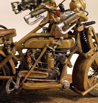 The engine parts also fell easily into place, except the one-piece exhaust pipe/muffler unit which required much fiddling and gentle bending to fit correctly into place. Squeezing the engine into the frame was also a chore since it's difficult to determine the right angle for the engine without also dry fitting the gearbox, fuel tank, and footboards. Spark plug wires, copper fuel lines, the throttle wire, the ignition wires, and an oil pipe were scratchbuilt and added to dress up the engine. The right side footpedal was the clutch and the left the rear brake: their connections to the gearbox and the rear wheel had to be scratchbuilt. The four springs on the saddle were replaced with wire springs. The tool box atop the fuel tank was too long to allow full movement of the handlebars so I cut about a third off the length; the rear rack was also too long to fit properly so I cut it down by about a third. By this time, the heap of parts was starting to look like a motorcycle, so I celebrated by going to Pittsburgh and Chicago to see my beloved Cubs play the last few games of the baseball season.

Sidecar & Machine Gun
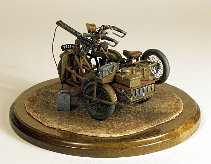
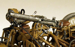 Returning to a smaller heap of parts, the sidecar assembly was pretty straightforward. The top frame piece had to be pinned to the frame bottom, the sidecar fender was thinned at the edges, and the machine gun mount was replaced with a longer rod to raise the gun. I added clamps to the leaf springs and replaced the cast coil springs on the seat with wire ones; the three pieces cast onto the ammo box cover were cut into separate pieces and the cover itself was replaced with a balsa wood one. All of the ammo boxes needed handles which I made from thin cloth which came with a fret of PE buckles in the spares box. The Vickers water-cooled machine gun is a lovely little kit in itself and needed no modifications beyond cleanup and drilling out the end of the gun barrel.

Painting
 At this point the subunits were primed and ready for painting and final assembly. I used a spray can of Testor's 'Flat Gray Primer' and Floquil gray 'Primer' brushed onto the leftover surfaces; I like this Floquil primer for metal as it's very thin and dries very quickly. The main color for the whole model was Testor's Model Master 'Field Drab', a medium dark greenish brown. Although many drawings show British WWI vehicles in green or O.D., knowledgeable minds say that brown is the more accurate color. Other colors for details were chosen with 'artistic license'; all of them Testor's Model Master line of flat enamels. Light weathering was done with acrylic washes of 'Dark Earth' and 'Rust', and the shadow details were picked out with very thin 'Burnt Umber'. A little drybrushing of 'Raw Sienna' along the edges and highlights and an overall spray with Testor's 'Dullcote', and voila! the model is done.
Conclusion
 All in all, this was an interesting and fun experience. Most of my modeling life has been spent building WWI biplanes and this was a nice change. Scale Link produces a variety of vehicles, artillery, and whole armies of infantry and cavalry in 1/32 and the determined modeler could have hours of entertainment building these. This build was "Part 1"--Part 2 will be the transformation of this model into a small diorama of the driver and gunner surprised by a ground strafing attack and wreaking vengeance onto the "Hun in the Sun". Stay tuned...

References
Military Transport of World War I, C. Ellis, Macmillan Company, NY, 1970
https://www.localhistory.scit.wlv.ac.uk/Museum/Transport/Motorcycles/Clyno.htm


![]()


