OzMods 1/48 de Havilland Canada DHC-4 CaribouBy David Charles | 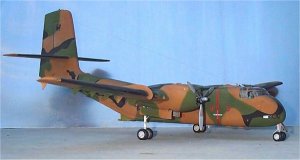 |
The Aeroplane
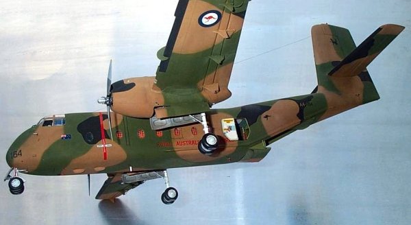
The De Havilland Canada DHC-4 Caribou was designed in the late 1950s. Its progress was helped along by a US Army requirement for a versatile transport and it eventually went into service in 1960 as the C-7. The Caribous really proved their worth for the US Army during the Vietnam War where they were also used by the Royal Australian Air Force. They were well known for their remarkable STOL performance. They could carry up to 32 troops or about 4 tonnes of cargo. Whilst being gradually phased out of US service they are still in use today in various military and civil roles around the world. After well over 30 years of RAAF service the Caribou is still used in Australia, albeit in small numbers. My subject, A4-164, was delivered to the RAAF in May, 1964 and is still in service.
The Kit
OzMods has produced a very good multi-media kit of the DHC-4 Caribou in 1/48 scale. The kit comes in a sturdy box and included are:
-
18 vacform parts
-
95 injected resin
-
16 cast metal parts
-
Decals for 11 RAAF and US Army aircraft
-
Complete assembly guides with detailed instructions
-
Printed photo references
-
3-view drawings
-
Resin engines, cockpit, wheel wells, aerials and flap hinge covers.
Construction
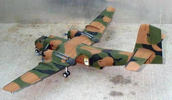
Right from the start I decided that this was one kit just waiting to be opened up. A truly impressive model can be built straight from the multi-media box but I thought I'd go a little further. I worked with sub-assemblies; the cockpit, the cargo bay (scratchbuilt), the fuselage (including those huge tail pieces), the wing (with engines). Because of the large size of this model (460mm long, 605mm wide, 210mm high), and the intricate masking needed for the finished scheme, I painted the wing before I mounted it on the fuselage.
Vacform Parts
 First I separated the vacform parts from their sheets. A sharp knife is used to score around all the pieces and then they are snapped from the sheet. Next they need to be scraped and sanded to size. To remove most of the plastic I hold a chisel blade at right angles to the mating surface and roughly scrape most of the excess plastic away.

Usually with a vacform kit I'd finish off by rubbing the part on a flat wet'n'dry paper surface. Because this kit is so big I couldn't get pieces of paper big enough for some of the parts! So it had to be done a bit at a time, very carefully, checking with the 3-view drawings regularly. By taping the two fuselage halves together I was able to cut the holes for the cockpit canopy, wing centre section and rear cargo doors.
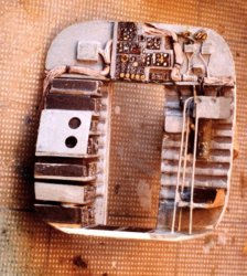
The Cockpit
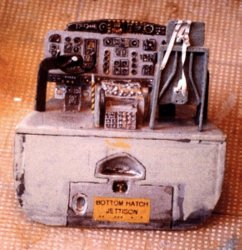
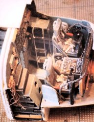 This is resin and it's quite comprehensive. I added the dash and rebuilt the overhead control panel with longer levers and lights. The pilots' seats are identical so I folded up the inboard armrest of each one and removed the moulded seat belts on one seat, rebuilding them in a different position. Behind the seats there's the drop to cargo bay level with escape hatches, radio gear and all sorts of electrical equipment on the bulkhead. Lots of cables of various sizes were added around the cockpit. These were made from various sizes of electrical wire.
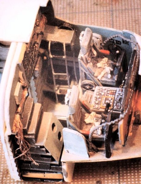
I was so pleased with the way the cockpit went together that I decided to open the top hatch. I cut the window out of the vacformed canopy and made a new hatch. That took a dozen parts with locking levers, air vents and so on and another EXIT decal. The detailed nose wheel bay is added to the underneath of the cockpit floor. And there's space to put a nose weight. I didn't put in enough!
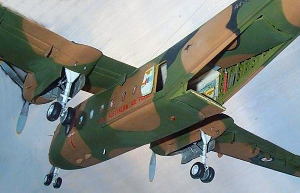
The Cargo Bay
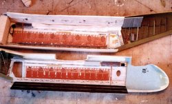
 The rear of the front bulkhead is detailed and the kit comes with a basic floor. As I planned to open one of the rear side doors, and the cargo ramp and door, a lot more detail was needed. The first job was to cut out the holes for the windows. This proved to be a difficult and time-consuming task as I struggled to get correct spacing, alignment and curve for each of the 16 windows. After thinning the plastic (so there wouldn't be a sill on the outside) I glued clear plastic strips over the holes. Then interior walls were added with matching window holes and a wide window sill on the inside.

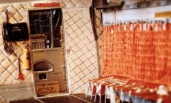
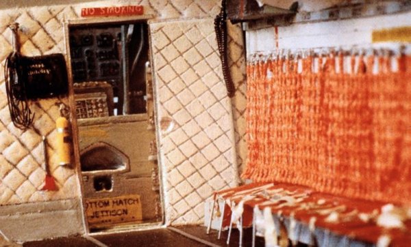
An obvious feature in many Caribous is the red webbing harness that forms the seat backs and is visible through the windows. After considering many options I found a white weaving mat in the local craft shop which had the correct pitch of squares. By cutting off some of the strands and bashing it flat with a mallet it started to take shape. Then a good soaking in greatly thinned Humbrol Matt Red resulted in an accurate colour. It looks right. Next came the tedium of push moulding all the seat bottoms. A wooden male mould was carved and then pressed into sheet plastic heated over a candle. Many times! These were then trimmed to the correct size, painted red and decorated with seatbelts made from masking tape with silver paint buckles.
 The seats are all hung on a framework of electrical wire. For variety and to ease later assembly I made the seats on the port side in the folded up position and those opposite folded down.
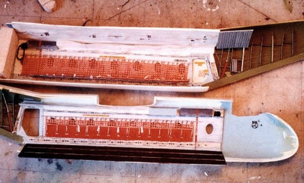
I made NO SMOKING, EMERGENCY EXIT and loading decals for the cargo bay and other places. Most of these were printed in black with the computer and then photocopied onto clear decal paper. After that I'd paint a coloured background in the model and lay the black decal onto it. The interior lining on the sides has to be taken just to the rear of the side doors. After that it's just bare framework and pipes made from sheet and tube plastic. The floor was made from plastic sheet scribed and painted with tie-down rings and other loading marks.
 There were lots of dry runs fitting everything in the fuselage halves and putting it all together to check that it was all the right size. For the roof lining I started with a sheet of .010" plastic with holes cut for roof lights and other things. I scribed the panel stitching with a knife. This lining was then tacked to a sheet of .020" plastic and held over a candle. The candle heat distorted the thin plastic causing untidy bumps and sags, which replicates the original lining. With all of that complete it was a relatively simple matter to make all the fiddly bits such as storage boxes, fire extinguishers, axes, headphones and all the usual cabling.
After making all of this the assembly process went like this:
-
Glue cockpit sub-assembly into starboard half.
-
Glue cargo bay interior walls in place.
-
Glue floor into starboard half.
-
CA glue all the seat props from seat to floor. Port side seats are folded up so they don't touch the floor.
-
Glue two fuselage halves together.
-
Slide roof in from the back and glue in place using the wing centre section cutout to help find the correct location.
-
Slide lining panels in from the back to cover the roof-to-wall joins.
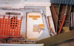 The side door came next. It was carved from laminated plastic to match the curve of the fuselage and had lining, a pocket and other fiddly bits added. The cargo door was made by bending a piece of plastic to the correct curve and then gluing trusses across it to maintain the curve. I clamped it all together and allowed a couple of days for the glue to set. The ramp is a smaller version of the cargo door but with more details including skirts and jacks. There's an odd shaped fairing that covers the underside of the ramp to fuselage join. I carved it from laminated plastic after the ramp was glued in place.

The Wing
 The basic wing comes in six vacformed parts: 2 outer panels and a centre section, top and bottom pieces. After preparing these parts I made a strong spar by laminating 3 pieces of .020 plastic. The drawings include a template for the spar. The three wing top surfaces were glued together with the spar in one operation. Plenty of liquid glue was sloshed around to get a good weld and the lot set aside to dry for a few days. The resin wheel wells were detailed with electrical wire then glued into place over the cutouts in the lower centre section.
After checking that the alignment of everything was correct the lower wing surfaces were glued to the top and to the spar, trapping the wheel wells solidly in place. This has resulted in a very strong box to support the undercarriage and underslung fuselage. The wing tips of the finished model flex slightly if they are used to pick up the model.
Once this basic wing is finished there're only a couple of dozen things to add. Fourteen of those are the flap actuators. Whilst the kit includes these in neatly done resin I filed a few more details into them and added a few more bits from stretched sprue. Detail photographs come in very handy at this point.
Wing fences are next and a template is included in the instructions. However, if, like me, you didn't get the perfect airfoil section of the wing, you'll have to work out the shape of the fences yourself. I did this by trial and error, using card and scissors until I achieved the correct shape. This was transferred to plastic and glued on. I made lift spoilers from square section plastic rod, cut lengthways on the diagonal to get the correct shape.
Trim tabs are provided in resin. I just sharpened the trailing edges then glued them in place. Landing light housings were cut out and pieces of clear sprue fixed in place with CA glue. This was then filed to match the curve of the wing and polished with a household cleaner to give a glass-like appearance. Before gluing in place I drilled into the back of the clear sprue piece and put a drop of silver paint in the hole to represent the lens. Then I painted over the back with an interior paint colour. These show through well when you've finished polishing the cover. By making the clear piece bigger than the actual light cover the join can be easily hidden under fillers and paint with just a small painting mask being put where the clear light cover goes. Vents were drilled in the leading edges and the aileron and flap joins rescribed to sharpen their appearance.
Engines
 Resin engines fit neatly into resin cowls that are CA-glued to the fronts of the wings and resin fairings with exhaust pipes and wing cover plates are glued behind them. I added plug leads and oil tanks around the engine then picked out the moulded details by dry-brushing silver and aluminium paints over a wash of matt black. The engines were rotated 180 degrees around the prop shaft from their position as shown in the instructions. The magnetos should be in the "10minutes to 2 o'clock" position on the engines rather than the "20 to 4" position shown in the instructions.
I spent some time hollowing engine air intakes and exhaust pipes then blanking them off deeper in so as to avoid the see-through look. I opened a small hatch on the top of each cowling too. These are all finely scribed in the resin straight from the box.
Tail Surfaces
 The tailplanes come in two parts: top full span and bottom full span. I glued the two parts together and when dry separated the elevators by cutting along the mould line with a razor saw. Any loss of plastic here, due to the thickness of the saw, can be made up in the next step. Scrap plastic was glued into the resulting gaps and they were reshaped before putting aside to glue back on later. This separation of the pieces results in a more realistic appearance as you can see that the elevators, especially around the balance portion on the outer tips, aren't joined.
I cut the rudder from the fin, filled the gaps, reshaped its leading edge then glued it back in place. Buffers were added at the base of the fin (rubber blocks to stop the movement of the rudder at full deflection) and trim actuators on the bottom corner of the rudder trim tab.
With all parts dry I cut holes through the fin and slid the tailplane through from one side. The holes I cut were too big and I had to fill in the gaps with scrap but this did allow me to move the tailplane to achieve correct alignment. With the tailplane tacked into place I filled the gaps with scrap plastic rather than tube filler as I wanted a strong and long lasting join. The scrap plastic was trimmed with the razor sharp craft knife and a tiny amount of filler was used to finish off. Then the elevators were glued in place.
Cockpit Canopy
 A vacformed canopy is provided with the kit. I cut it carefully from its sheet (multiple passes with the sharp knife; patience needed here). I didn't cut up to the window frames but about 5mm away from them. Then I rebated the fuselage plastic around the canopy hole to match the extra that I left on the clear bit. To cut the rebate I pencil in a guideline then score around that line with the knife. After that I scrape off the plastic with a knife. When the canopy is installed it sits on that lip and makes a strong joint. Also, any filling and sanding to cover the joins is moved 5mm away from the clear parts. As mentioned earlier I opened the top hatch and I did the same with the pilots' sliding windows. The overhead panel was glued in place before attaching the canopy with white glue.

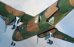
The Wing Goes On
The wing sits in cutouts on the top of the fuselage. By carefully trimming all the parts I found that the wing dropped into place neatly and the joins needed only a minimum of filler. Everything was propped up on jigs of paint bottles and clothes pegs to get the alignment just right. At this stage a new problem arises. Where do you put a model that's 460mm long and over 600mm wide? It hangs over the side of every bench and attracts the hands of pre-school helpers!
Undercarriage
 Time for the undercarriage. The legs are cast metal. I tidied them up with a file, added brake lines and a different torque link for the nose leg, then CA-glued them in place. The resin undercarriage doors have the internal detail moulded in place so just needed painting before tacking on. I added door jacks made from electrical wire with the plastic insulator still in place along half its length.
The wheels are resin and need only a few whisks with a file to tidy up. I flattened the bottoms to give them a better sit. They don't need bulging sides unless you're going to model a 'Boo that is in dire need of a service! The wheel wells and doors were painted matt aluminium, washed with matt black and dry brushed with silver. Hoses and wires were picked out in a variety of colours. Wheels and legs were painted matt white, washed with black and dry brushed with gloss white and then lightly with silver. The tyres were painted Humbrol matt black and when dry rubbed with a cloth to give a rubbery sheen.
With the model on its wheels it appeared to be sitting too high when compared with photographs. I broke the undercarriage off and shortened the legs by about 6mm. I sawed through the legs, removed a 6mm section then drilled down the centres of the legs, inserted a steel pin (sewing pin with the head removed) and epoxied the halves back together. (Joints filled and smoothed, legs repainted, brake lines replaced!) Mounted back in place and with the top of the nosewheel leg suitably shortened the model now had what I considered to be a good "sit". Expert opinion has since informed me that these mods were unnecessary as the different heights would simply reflect the different fuel and cargo loads of the aeroplane at any particular time. It's all part of the fun.
At this stage I discovered that I hadn't put enough weight in the nose and it was a definite tail sitter. I fashioned some "baggage" out of a lump of lead (an old wheel balancing weight) and glued it under the seats at the front of the cargo bay. Very long tweezers were used to get it in there and it's hardly noticeable. Problem solved.
Finishing
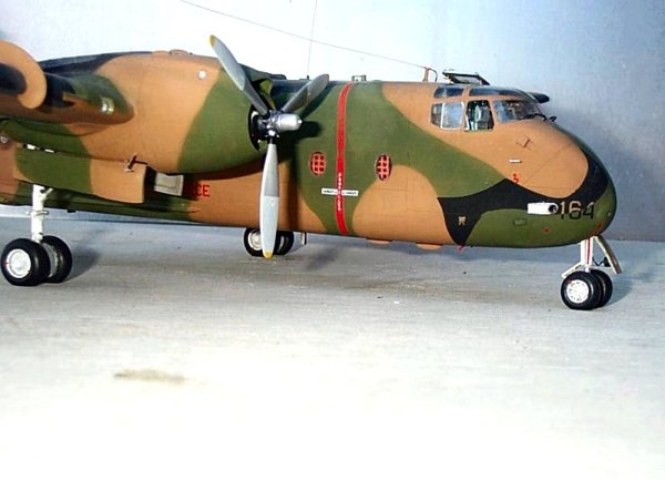
 Various fixed and wire aerials were added as were lights, a beacon on the top of the rudder and drain pipes. Windscreen wipers were made from scrap and the resin sensors/pitots were thinned and CA-glued in place and a final coat of clear matt Humbrol was misted over everything to give a matt/satin finish. The props and hubs are resin parts and require little more than cleaning up with a file before painting. I painted them aluminium, washed with black and drybrushed with silver. The spinner was then brushed silver and the blades painted two shades of an aluminium/grey mix. The badges on the blades are hand painted representations.

Paints & Decals
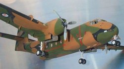
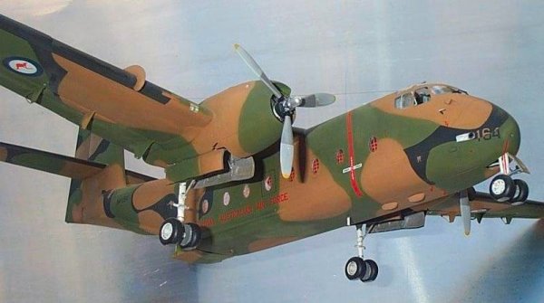
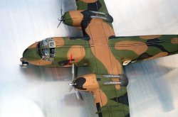
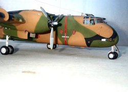 I finished this model as RAAF A4-164 in its tan/green black scheme. I painted with enamel and decalled before joining the wing to fuselage. The clear bits and wheel wells were masked with Maskol. The doors were tacked in place so that the camouflage pattern would be correct. Tan was sprayed first, then everything was masked for green and black was applied last. I tried to achieve a soft but very tight merge of colours by cutting paper masks for all areas and then holding them about 1mm off the surface as I sprayed. This was partially successful but I had a lot of respraying to correct overspray.
I sprayed two coats of Johnson's floor polish (its called 'Shine Magic' in Australia) as a base for the decals. And now another problem arises. Every Caribou in Australian service is different. There is no requirement to strictly follow the camouflage pattern. So, numbers and words have different colours depending on the background colour. Even though OZMODS supplies a wide range of decal options my choice of subject was outside that range. As a result I used some of the kit decals, and made the others myself.
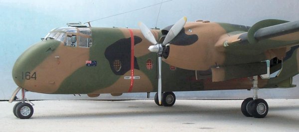
The underwing roundels, prop warnings, Australian flag and "Royal Australian Air Force" on fuselage sides are kit decals. They sat down very well on the glossy surfaces with no sign of silvering. For the A-numbers on nose and fuselage sides I used a mixture of kit decals and black dry-rub lettering. Where they needed to be tan coloured (on black surfaces) I applied the black letters first then painted the appropriate parts tan with a fine brush during those times when my hand wasn't shaking too much.
The fuselage kangaroos and tail 38 Squadron badges were sprayed through masks I cut from paper. Just before I spray I lick the back of the paper mask and the slight dampness is enough to hold the mask in place long enough to get a neat spray. Heavy drinkers should avoid this technique unless they shave their tongue. The wing-walk lines were done with an old draughting pen using well-thinned Humbrol matt black. I practised on scrap plastic first to get the correct viscosity of paint and width of line.
The broken lines around the emergency exits were done with a fine-tip permanent marker. It's important to get the type that won't react with under- or top-coats. I bought it over the counter at the local art supplies store. Just before the marker ink set I wiped most of it off with a soft cloth to give the toned down appearance.
Conclusion
 Since my first flight in the Caribou in the late 1960s, watching the engines rattling about in their mounts, compliments of the Australian Government, this has always been a favourite type. The opportunity to build a model in 1/48 scale was always desired. OZMODS has sated that desire with this great multi-media kit. I have seen examples built straight out of the box and they do make handsome models. And for those suffering some type of syndrome involving the addition of minute detail this is the model for you, too. Just clear a bit of space in the display cabinet in preparation.
References
-
Wilson, Stewart Dakota, Hercules and Caribou in Australian Service Aerospace Publications P/L, Weston Creek, 1990. ·
-
38 Squadron, RAAF for help with details. ·
-
OZMODS, https://www.ozmods.com.au


![]()


