CMR 1/72 Supermarine Seafang FR 32By Ted Holowchuk | 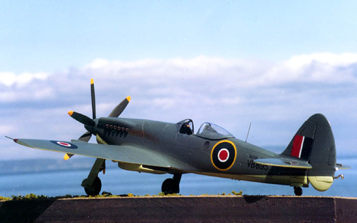 |
History
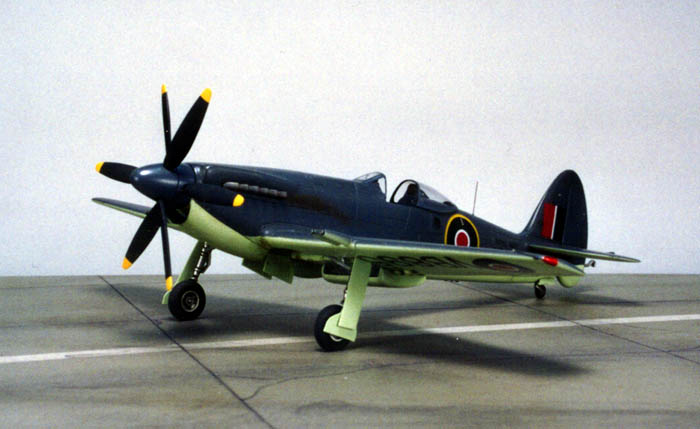
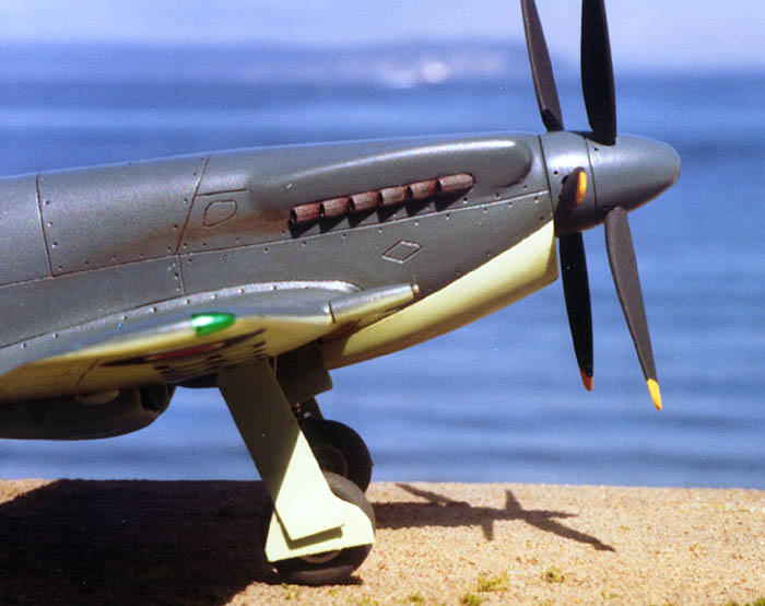
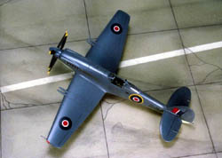
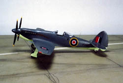
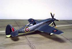
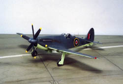
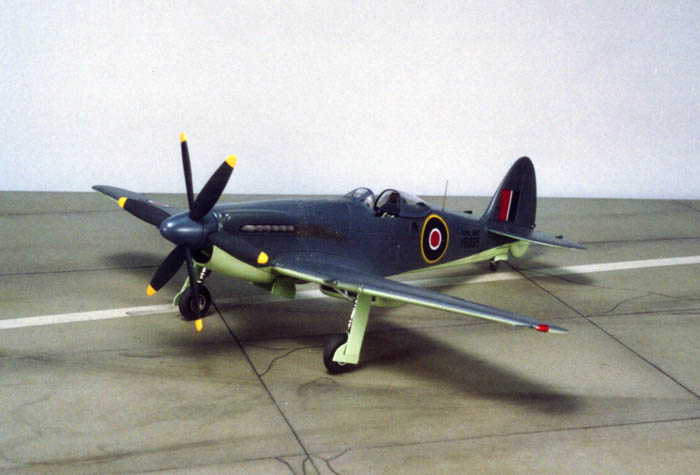
 The Seafang was the navalized version of Supermarine's Spiteful. They were the end of the Spitfire/Seafire line. 17 Spitefuls and 18 Seafangs were built. It is claimed that a Seafang achieved a speed of 494 MPH; making it, if the claim is valid, the fastest propeller driven aircraft ever built in the UK. The Spiteful/Seafang has been aptly described as, "A Spitfire too far." Another distinction it has is that its wing was adopted for Supermarine's Attacker jet fighter. The Seafang was powered by a Rolls Royce Griffon 89 engine driving two three-bladed contra-rotating propellers. This aircraft was the final piston engined naval fighter built by Supermarine. The writing was on the wall - the jets were coming. This particular aircraft, Seafang FR 32, VB895, was flown by noted test pilot Mike Lithgow in May 1947 during deck landing trials on HMS Illustrious.
The Kit
The instructions are on two European A4 size sheets. The first has an exploded drawing of the model with arrows pointing to the (approximate)  locations of the parts, along with a couple of notes. The second sheet has a side and a front view drawing on one side of the sheet and drawings of both sides and of the top and bottom of the aircraft for decal placement on the other. Colors are called out by FS number. I like that. Also included is a brief historical note about this aircraft and its pilot.

The kit parts are all resin pieces of varying quality. The fuselage halves, spinner and wings are made from a medium gray resin and are a little crude. The fuselage halves are of slightly different lengths and the cross sections at the front are not the same on each half. Noticeably, the humps over the cylinder heads are quite different in shape and location on the two fuselage halves. This ought to be fun! The panel lines don't match from the left to the right fuselage halves. The wing roots are slightly staggered from  both a top view and a front view. Each wing is slightly different in length, panel lines, gun locations and wheel wells. There are "pot-hole" sized rivet indentations on the wings and fuselage.
The rest of the resin parts are a light tan color. Some of these seem to be of better quality than the gray parts. Could the masters have been made by two or three different guys who didn't talk to each other or compare parts?
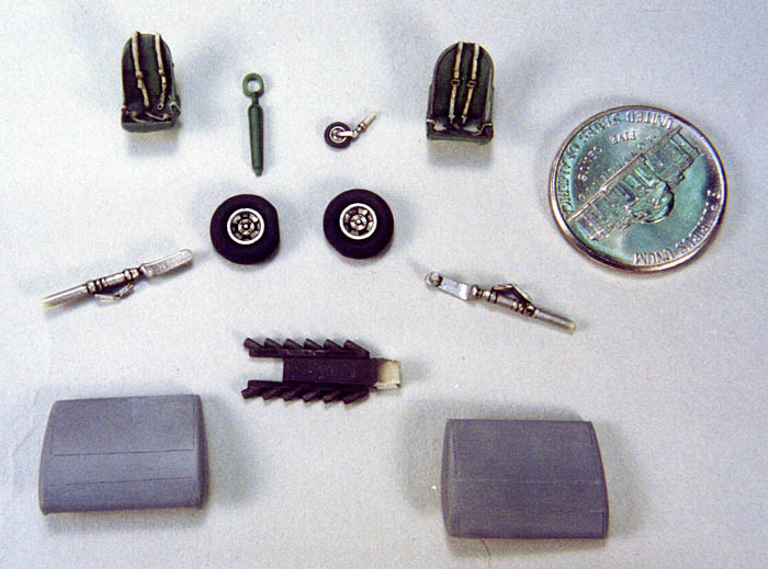
One note: The wheels/tires master had to have come from an injection-molded kit, because the resin parts have ejection pin marks on the tires! Hmmm; very  interesting. The rest of the resin parts were good to so-so. The seat looks awfully big for 1/72; we will see.
Two vac form canopies are included. That's a good idea.
The decals look good, with all the markings needed for this one aircraft. The register of the roundels seems to be a bit out, but it is late at night, and it may just be an illusion. We will see; maybe I'm just losing it. The decals are printed by MPD.
The Build
I began by washing all the parts. The gray resin parts had an unusually slippery feel that I did not like.
 Fuselage & Propeller
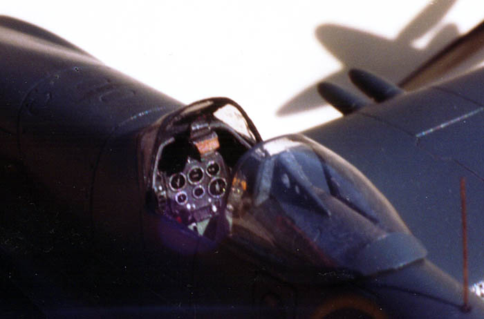
Inspection of the inner fuselage revealed sparse detail with some of the ribbing broken or missing. Some air bubbles were also evident in the resin. The broken/missing ribbing was replaced with strip styrene and the bubble holes were filled with putty and super glue. I sanded and dry fitted the floor and the rear bulkhead. Oh yeah - the seat; it still looked too big and it took up a lot of room. To hedge my bet I dug a Cooper Details Spitfire seat out of my parts box.
The cockpit was painted with Interior Green, FS34227, as specified by the instructions. When dry, these parts were oil color washed, dry brushed and dull-coated ready for installation. Oh yeah - I also painted both seats.
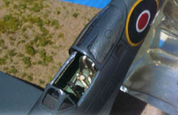 The instrument panel looked nice, but was also too big. I carved material out from under the coaming with a rotary bit. Be careful; you don't want to go through. I wonder how I know about that? The panel still didn't fit, so a little filing and sanding on its ends fixed that. The panel was painted dark gray, washed with black oil color and dry brushed with off-white and silver. I picked out knobs, switches and such with red, yellow and silver then dull-coated the whole thing. When dry, I used drops of clear epoxy for the glass faces of the instruments. The panel finished up nicely and looked good.

The floor and rear bulkhead were glued into one fuselage half with a gob of epoxy putty. A little fiddling with the fuselage halves resulted in a reasonable fit of these parts. The instrument panel was glued into the same half with epoxy putty. More prodding and adjusting produced a decent fit.
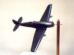
 I used an old trick of mine to make a removable propeller assembly. (Read; It falls out! Ed.) SEE PHOTO. I drilled into the back of the spinner and epoxied a length of 1/16" brass tubing in the hole. I used a homemade fixture to center the prop shaft, and keep it at 90° to the spinner back plate.
Before gluing the fuselage halves together a large gob of epoxy putty was jammed into the nose of each fuselage half to prepare the nose for the propeller assembly. The fuselage halves were glued using epoxy and super glue, working slowly, trying to get as good a fit as possible. The fuselage halves, of different lengths - remember - were aligned on the cockpit, resulting in the nose and tail being slightly off. After the fuselage was glued up and the nose trued up, an oversize prop shaft hole was drilled in the epoxy in the nose. A length of 3/32" brass tubing was epoxied into the oversize hole. The spinner/prop shaft was slipped into the 3/32" tubing and moved around until the spinner sat squarly on the nose. This was done using the old "Mark One Eyeball" system. When everything was as well lined up as possible, the spinner/prop shaft was removed and everything was left to really set up. The epoxy putty takes about 15 minutes to set up. It worked pretty well and resulted in a reasonable fit. However, some filling, filing and sanding were needed to get a decent transition from the spinner to the nose.
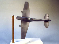
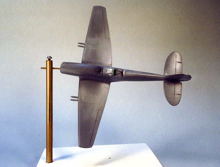
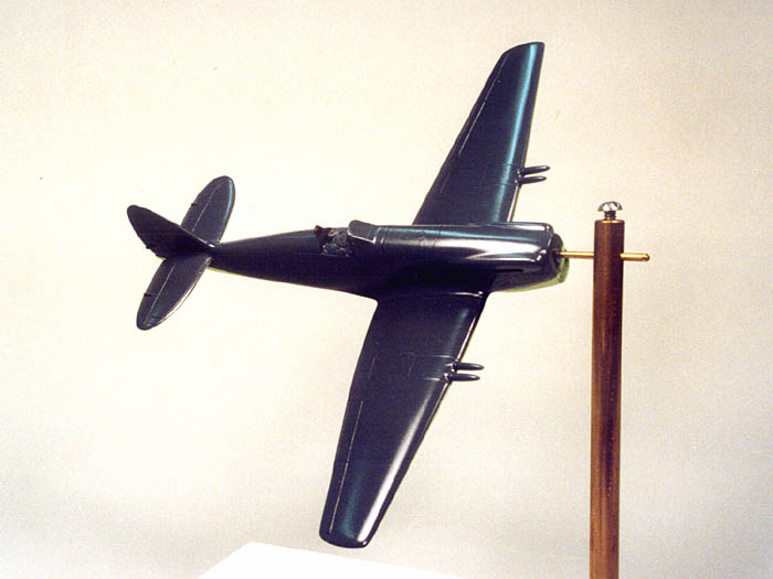
 SIDE NOTE: That brass tube in the nose was also used to hold the model while painting and working on it. SEE PHOTO. In addition to the work stand in the photo I used a tool, which consists of lengths of 1/16" diameter wire stuck into each end of a wood handle. The wire on one end was slipped into the nose in order to hand-hold the model while painting. When done, the wire on the other end was stuck into a hole in a piece of scrap wood. This let the model sit nice and safe while drying.

Oh! Oh! I forgot: Before gluing the fuselage halves together, I did a dry fit and tape-up of the halves to check the wing root and tailplane fit. I measured, marked and cut off about 1/16" from the longer wing. Hmm! Maybe I should have added 1/16" to the shorter wing. Both the wings and tailplanes are butt jointed to the fuselage and I don't trust the strength of this type of joint. I measured and drilled holes into the ends of the wings and tailplanes. Oversize holes were drilled into the fuselage halves to match the locations of the holes in the wings and tailplanes. The oversize holes allow adjustment for a good fit when glued.
 All the fuselage's differences in length, configuration, bulge shapes, etc., etc., noted in the beginning, then came up to haunt me. The nose/spinner area was carved and sanded to a reasonable contour and profile. Filing and sanding brought the tail section area together. All those pothole sized rivets were filled and replaced with prick marks made with a pointed scriber. The panel lines were re-engraved to straighten and line them up. The vertical panel lines did not line up over the top, or under the bottom, of the fuselage from left to right. "Darn it!" I said. What now? I know. There will be no panel lines over the top, or under the bottom, of the fuselage. Solved that one.

 I left those engine bulges 'till last because I'm a coward. They were awful. I puttied, filled, filed and sanded ad nauseam until they still were not right, but were better and as good as they were going to get. The exhaust locations were revised slightly and the good-looking kit exhausts fitted into their slots.
The rudder top and bottom units were glued together. The tail hook hole was drilled out. The whole vertical tail was sanded and rescribed. Holes were drilled into the bottom of the fin and into the top of the fuselage. Short lengths of wire were used to strengthen the joint by gluing them into those holes and using epoxy to glue the tail unit onto the fuselage. The slow setting epoxy let me use the old eyeball to adjust the parts for as reasonable a fit as I could get.
Wings & Tail
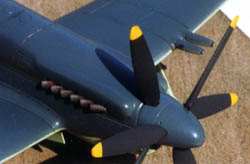
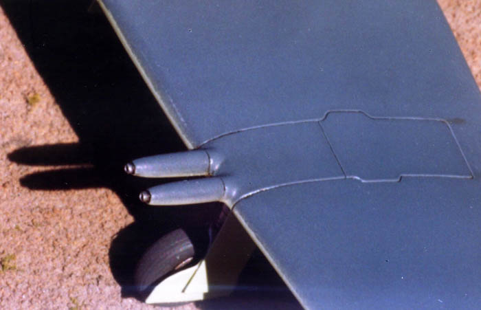
I rechecked the wings for size and configuration. Some filing and sanding soon had them looking kind of similar, except for the scribed lines, cannon locations and wheel wells, which were different on each wing. I cut off the cannons and drilled the front of 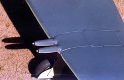 each cannon fairing to accept appropriately sized metal tubing for the actual cannon barrel. Each was chucked in a Dremel tool and sanded round, eliminating the as-cast oval cross sections. The wings were measured and marked to locate the cannons. Holes were drilled at each location to accept a length of plastic rod the diameter of the base of the cannon fairings. The rod was glued into the holes to create the stubs of the cannon fairings and putty and primer were used to build up a small fillet around the base of each stub. All scribed lines were filled and the wings were rescribed. My limited references did not indicate where the panel lines should be. I chickened out and only scribed the aileron and gun bay panel lines. These were supposed to be laminar flow wings and so, like the Mustang, should have no other panel lines showing. Right?
The tailplanes were rechecked and a little trimming and sanding resulted in good fit. They were also different left and right, but not as bad as the wings, so I left them uncorrected. The panel lines seemed to line up pretty well from left to right.
 I attached one wing at a time adjusting the wing pins in the oversize fuselage holes. The first wing joint was allowed to cure before I started the second one. I checked and rechecked from every direction to get as good a fit and alignment as possible. It's as good as I could get it. Not great. Still slightly out of whack, but that's what I had to work with.

A similar process was repeated with the tailplanes, squaring them up with the wings and the vertical tail.
When all the parts were set and the epoxy had cured, I used filler, files and sandpaper to trim the fit of the wing and tailplane roots. The cannons were now glued onto their stubs using pins and epoxy.
 Turning my attention to the under side of the model, I was not surprised to find that the wheel wells were still different in shape, size and location. No miracle had corrected their problems while I wasn't looking. After careful consideration and a few choice phrases, I left them alone.

The underwing radiators were trimmed to fit the wings in a reasonable manner. The landing gear struts, wheels and gear covers were cleaned and painted.
The cockpit was masked off and all parts were primed with my favorite automotive primer. All parts were then rechecked. More filling, filing, sanding and chasing of panel lines was needed. This whole prime-sand-prime process was repeated a few times on the main assembly trying hard to make a silk purse out of this sow's ear. By the time I had finished, it didn't look too bad; as long as you didn't look too close.
 Canopy
I cut the canopy from the surrounding material and then cut the windscreen from the canopy. I cut along the framework molded into the part and found that the framing between the canopy and the windscreen was not square with the canopy centerline. Also, the base edges of both sides of the canopy/windscreen were slightly flared and not symmetrical side-to-side. I swear I cut the parts correctly on the indicated frame lines. What else? At this point I was ready to round file the whole thing. But, having made a commitment to Chris to build this thing, I instead went into the WTH Spares & After Market Department looking for possible replacement clear parts. No luck! So I took a deep breath and went to work on the kit parts. First I dipped the clear parts in Future floor wax three times trying to clear up the slightly cloudy, rough, vac formed parts. When dry, the windscreen was glued to the fuselage with tiny drops of super glue and then a liberal application of white glue was applied as both a bond and gap filler. When dry, I masked the clear parts with Bare Metal Foil and the new Tamiya masking tape. A lightly sprayed coat of black primer was applied to the framing of the clear parts in preparation for the final external color. A little sanding of the windscreen-to-fuselage fillet had this area looking pretty good.
 Painting (Additional Photos Here)
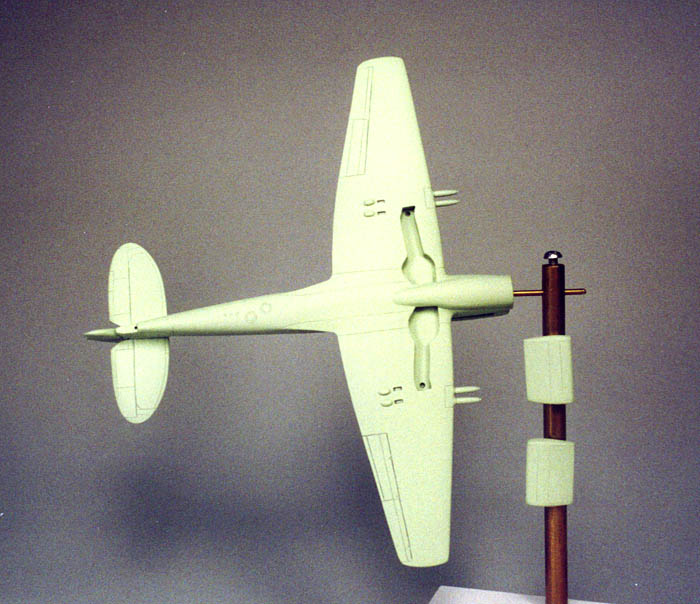
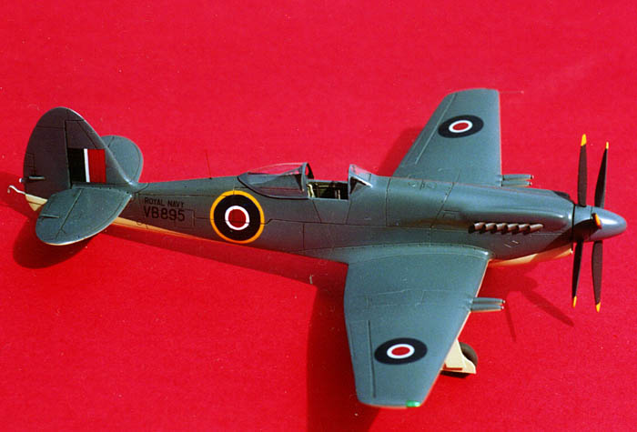
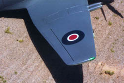
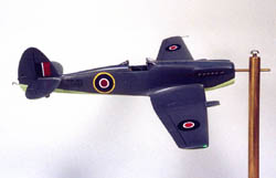
Believe it or not - this thing was now ready to paint! The underside, gear doors and radiators were painted with the recommended "Sky", FS34583. When dry the Sky color was masked off and the top of the aircraft and the spinner were painted "Extra Dark Sea Gray", FS36099. The masking was removed and the whole thing was sprayed with a couple of light coats of clear gloss auto lacquer. Hallelujah! Decal time! Light could be seen at the end of the tunnel. Or was that the headlight of an oncoming locomotive? The decals were great; easy to apply, good coverage and no silvering. What else could I ask for? The only problem was me. In order to touch up a little paint glitch near the canopy area I managed to let a piece of tape touch the roundel on the right side of the fuselage and lifted off a fairly large piece of the decal. "Oh darn!", I said. After much swearing, and thinking, I ended up hand painting most of that roundel. It WAS an oncoming locomotive!
 Back To The Propeller
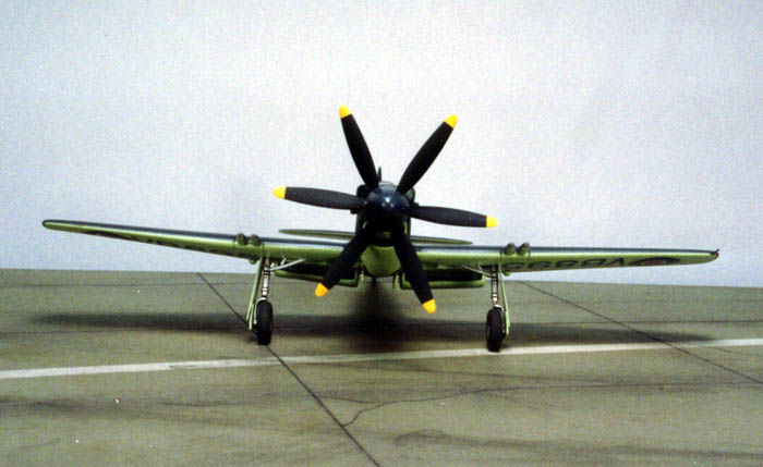
I drilled out the blade holes at the points marked by small indentations molded into the spinners. The blades had already been cleaned up, thinned and painted dark gray with yellow tips. I made a fixture to align the blades in their proper 120° spacing. I used epoxy glue again to give me some working time. This process takes quite some time, but allows me to position things just right. But - the prop holes, that I had drilled in the marked positions on the spinner, were not positioned 120° apart like my fixture was. I guess I should have checked first and used my fixture to locate the prop holes instead of trusting CMR to have gotten it right. Darn! I was stuck with the holes I had already drilled, so I made the best job of it that I could and fudged the blade positioning around until they all looked right, even though they were wrong. I finally completed this job and looking it over, rather pleased with my work, I dropped it and broke off a blade. Aurghg! I redrilled the hole and remounted the blade. And, would you believe? I dropped it again and had to replace another broken off blade. But, anyway, it was now finished and ready for installation.
 Painting Resumes

While I had been working on the prop assembly I had also been spraying a few coats of clear gloss auto lacquer onto the painted model to build up some thickness over the decals. When dry I lightly sanded the decal areas to eliminate the decal edges. Another final coat of clear gloss was applied to check my sanding. When this was dry I lightly buffed the model with Scotch-Brite and sprayed everything with a light coat of clear semi-gloss auto lacquer for my final finish.
Final Assembly
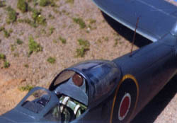
It was now time to remove the masking and proceed with final assembly. OH yeah? The rear edge of the windscreen was still off square. Some very fiddly, fine cutting with a sharp scalpel resulted in a much better look. I made, painted and installed the 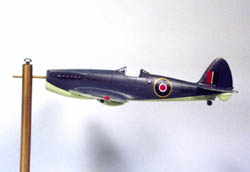 roll-over framework behind the cockpit; none was included in the kit. I made and installed a stick and a gunsight. The kit seat would NOT fit into the finished cockpit. No way! The Cooper Details seat that I had painted as a backup went in just fine and looks great. White glue was used to fit the canopy in a slid-back position. A short length of monofilament nylon was used for the VHF antenna on top of the fuselage behind the cockpit.

I turned the beast over and fitted and glued the radiators into their locations. The fit was not great. A little filler, Sculpey, was pushed into the gaps, cleaned up with a toothpick and touched up with the Sky color paint.
 The landing gear was attached next. The wheels were glued on and the aircraft was turned over and put down on its landing gear and it promptly squatted as the wheels splayed out sideways like an old duck. Now what? The resin landing gear yokes were too weak to support the weight of the model. I made replacements for the large gear doors from .010" sheet brass and made them a bit longer than they should have been. These were super glued into the wheel wells at the top, that's what the extra length was for. The lower ends were then glued to the small wheel covers, which were glued to the lower gear yoke making a very sturdy structure that does hold up the model. Throughout this whole process I was constantly tweaking and prodding the parts to get a reasonable looking fit and alignment.

 The arrestor hook, pitot tube, tailwheel and tailwheel doors were glued on. The wing tip lights were painted on. The camera window behind the cockpit on the left was painted dark gray and gloss coated. What was next? There were no parts left. I was finished! The damned thing didn't look too bad. Not a prizewinner, but an acceptable model. Boy I sure don't want to do something like this again.

Conclusion
To the best of my knowledge this is the only 1/72 Seafang kit around so, I guess, this is it. Overall, it's a real tough build with all the problems encountered, aside from my own ham-handed ways.
 I am pleased that someone has put a kit of this unusual subject on the market but I must say, having had a little experience myself with making masters and with resin casting, that a little more time and care spent taking care of the details of mastering the parts would have resulted in a dynamite kit of a rare aircraft. As it is, if you want a Seafang, have a go at it - and good luck. This kit is not for the faint of heart. A good supply of time, diligence, effort and vocabulary will be an asset.
Remember - model building is fun.
References
-
Spitfire - A Complete Fighting History: Alfred Price, Promotional Reprint Co., Enderby, UK, 1991, ISBN 1-85648-0151.
-
Spitfire - The Story Of A Famous Fighter: Bruce Robertson, Harleyford Pubs., Ltd., Letchworth, UK, 1960.
-
FineScale Modeler Magazine, March 1998: Jack Smith's article Modeling The Supermarine Spiteful.


![]()


