RVHP 1/72 Resin Wight QuadraplaneBy Dennis Ugulano | 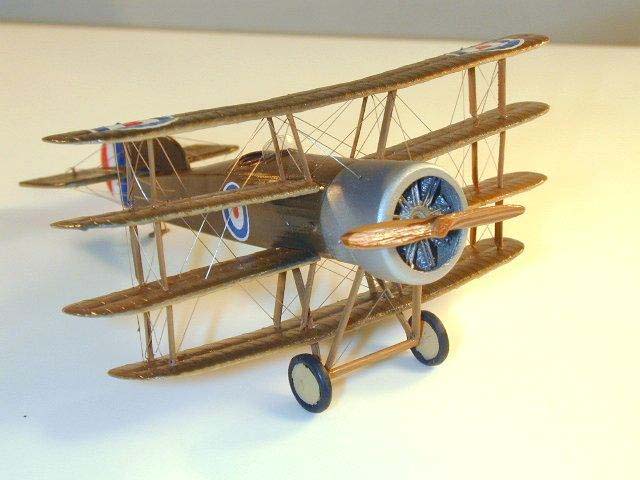 |
History
 |
 |
 |
 |
 |
 |
 |
 |
 |
 |
 |
 |
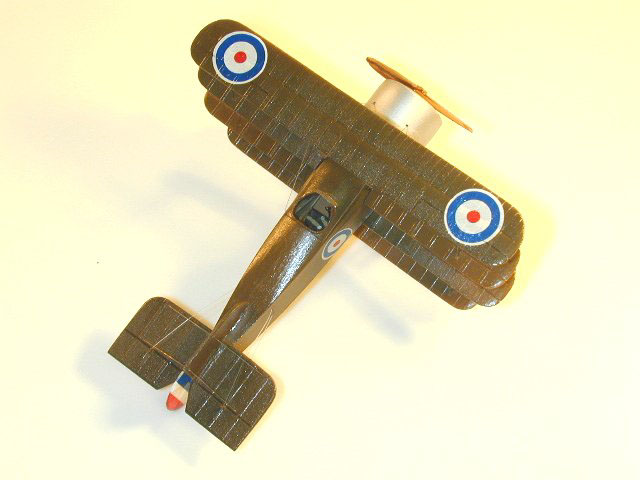
The original design was a private venture with three wings of equal chord and span, each wing having ailerons. The fourth wing appears to be an afterthought to a normal triplane configuration with the leading edge cut out for the wheels. This wing was so close to the ground that the tailskid was almost 3 feet long, keeping the plane level on the ground. It was powered by a 110 hp Clerget.
The second version (rebuilt as No. N546) had a large tail unit and the lower wing was moved above the wheels. It underwent flight trials in February 1917 with the test pilot giving a display of violent aerobatics: rolling, zooming and looping. It was returned for further modifications.
These modifications entailed a new set of wings, moved aft a few inches, with ailerons fitted to the top two wings only. The undercarriage wheels were also moved a few inches further forward and by this time the plane had a normal tailskid.
This final version attracted enough interest that a contract was awarded on 13 November 1917. However, its performance was not sufficiently good for the type to be given a production order. Because of this, the plane remained a prototype. It was written off on 2 February 1918.
It is the final version that is the subject of the kit and this build up.
The Kit
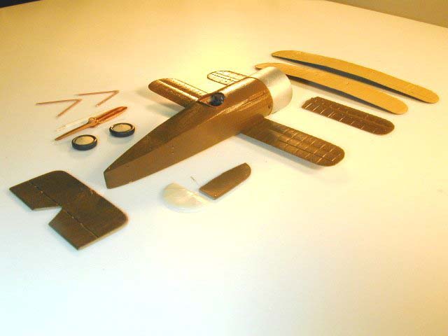
The Fuselage
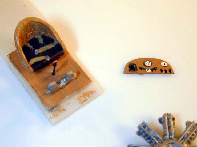
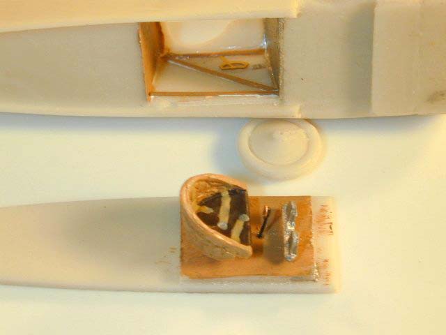
With the exception of some interior framing, the kit is 100% out of the box. I started by painting all of the interior parts, engine and prop. The instrument panel is from my imagination as there are no photos of the interior of this plane. I just add something so people can marvel at how real the interior looks using the normal human eye. Since I work with a 2 1/2 magnifier, I know it's nothing more than black and white dots.
The interior is a hole in the solid resin body and just a few pieces of square stock is added to give a frame look. The throttle quadrant was added just as an additional touch.
The instrument panel was attached from the bottom.
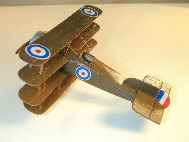
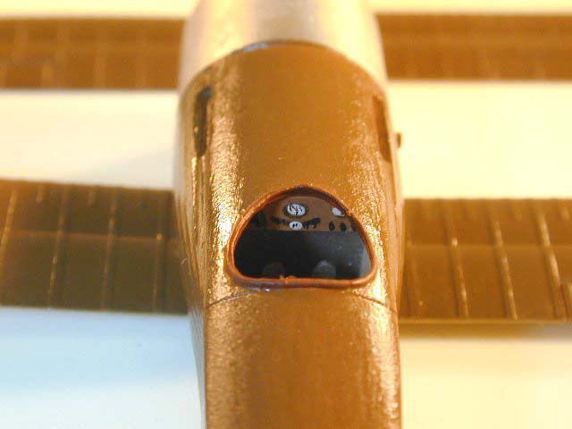
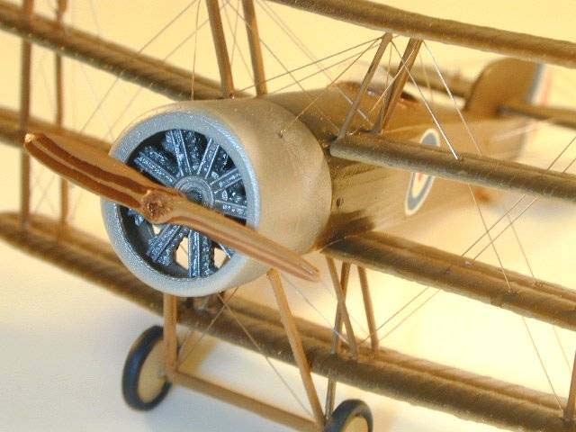
After the interior is complete, the entire assembly fits into a slotted area on the bottom of the plane. With minor trimming along the edge, this section fits perfectly. The cowling was then added and the fit was good, with just a little sanding needed to get it right. The cut out in the cowling is large enough that the engine can be added last, making it a little easier to paint. Putty and sanding complete this section of the kit. I painted the fuselage at this time because there is nothing else that needs to be added to the fuselage. A gloss coat was added, and then the decals were applied.
The Wings
The wings are very delicate but with very little flash and I found no voids in the resin by holding them up to a light. The ribs are little heavy but I had no desire to sand them flat and add a finer rib. Besides, the wings are so delicate, I would venture to say that they would be destroyed in the attempt. After sanding, painting and decals the wings are compete.
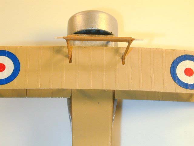
Tail Assembly
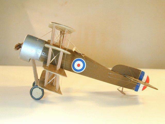
This is, in my opinion, the weak area of the kit. I was never able to fully understand this section. After trying to make the stab and the fin work together, the conclusion I came to was the hortizonal stab is too thick. If I were to build another kit, I would make the stab out of thin sheet stock and I think it would then fit. I finally sanded a V shaped section out of the stab to at give it the appearance of fitting correcting. It would later prove to be too thick even with this drastic procedure. Anyway, it was assembled, painted, decals applied and attached to the fuselage.
Undercarriage Assembly
Here is where I departed from the exploded drawing recommendations. I made the undercarriage legs one piece from airfoil shaped stock and then cut a hole in the wing to correspond with the legs. After the legs are attached, the bottom wing is not trapped by the legs but is not fixed in its final position.
Wing Attachment
Here is what appears to be the most difficult part of the kit but after it was all said and done, it wasn't that bad. Great care and constant alignment is necessary to make it work.
There is a notch for the third wing and I made an irreparable mistake here. The dihedral is set in this wing but it doesn't fit exactly right. I trimmed and thought I had it in place but evidently I pushed it a little too hard and lost the dihedral. By the time I caught it, I was committed and could not turn back.
This wing is where I started aligning the wings. All of the struts have been cut at this time using the line drawings in the plans. The strut locations are predrilled in the wings and their positions are correct.
Before the wings are attached, the wings must be drilled for the rigging that runs through the wings. Using the plans, these holes are marked in place. There are four holes each on the second and third wings. After the positions are marked, the holes are drilled at an angle to match the direction of the rigging. This way the rigging will flow from cabane to lower position strut on the fourth wing.
Returning to the wings, I attached four struts to the fourth wing that is trapped by the undercarriage legs at their proper angle. After they are dry, this wing is attached to the third wing. After checking the wing stagger, the fourth wing is attached to the undercarriage legs. The second wing is the easiest, as it has locating slots on the fuselage. It was attached to the fuselage and then the struts were added and glued. Continue up with the fourth wing and attach the outer struts. After the alignment is correct, I added the cabanes one at a time.
Another and probably easier way of wing alignment is to drill holes completely through wings two and three and insert a one piece strut. The first and fourth wing could then be attached and the dihedral checked before gluing the second and third wing. I thought of this but was reluctant to drill holes through the only set of wings I had. I would not have lost my dihedral if I had use this method.
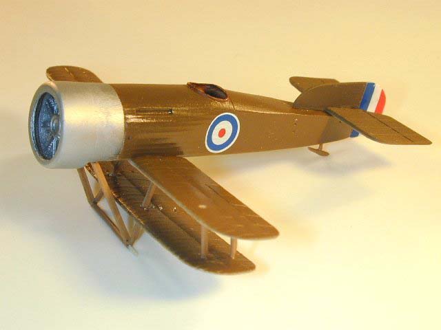
With the wings attached the model is basically complete. I rigged it using nylon thread (DURAS), added the engine, prop and windscreen. Total building time is about 15 hours.
Conclusion
This is a very nicely engineered kit of a very complex subject and RVHP is to be commended. There were no voids in the resin which has been a problem with past resin kits. My main complaint is the same as the rest of the resin kits I have built. There is no reference material listed. Without Len's material, there would be areas of this plane that you would have to build out of blind faith. All in all, I am pleased the RVHP's offering and if you are into building odd and "one of" kits, the Wight Quadruplane will be right up your alley.
With Thanks to:
First: The kit is released by RVHP produced by Robert Vele of the Czech Republic. This a 1/72nd scale polyurethane resin kit of an aeroplane that only two were built. Lubos Vinar of VAMP Mail Order provided the kit for review.
Second: Bob Pearson, who allowed me to talk him out of the kit so I could build it. You can read Bob's review of the kit in the May 2001 Internet Modeler
Third: Len Smith, who sent me nine pages of text and photos so I could actually build this kit.


![]()


