Converting the Revell/Matchbox 1/72 Flower into an RCN Corvette: Pt 2 | 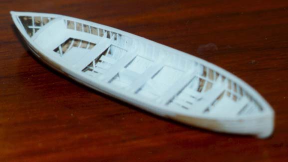 |
As built, the Flower Class Corvettes were fitted with a 16' wooden dinghy on either side of the funnel. These were later moved slightly forward when the focsle was extended. It is at this later location that the Matchbox/Revell kit represents. However, upon extending the focsle most Canadian corvettes replaced their two dinghies with one 27' whaler on the starboard side. The former port side location was used for additional Carley Float stowage. This month we shall make a 27' whaler using the two kit boats as the starting point.
When I decided on an RCN Flower, I also decided I would eventually need the proper boat for it. A search of the internet turned up two commercial options - Quayside offers a complete kit of one for around $30, and Billing Boats have a 1/96 scale lifeboat measuring 95x25mm. The former was more than I wanted to pay, so I decided on modifying the Billing's offering. A quick calculation came up with a length of 114mm for a 27' length in 1/72 scale. Therefore my plan was to cut the Billings boats at 13mm past the centreline and join the resulting long bow to the long stern. While waiting for the online company to reply to my request (it was a Friday night), I got energetic and took a look at the kit boats .... hmmm, perhaps they have some potential.
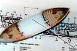
Before I could change my mind, I grabbed my trusty Dremel Mini-Mite and quickly cut each dinghy in half and discarded the stern sections. I wasn't too careful about how straight my cut was so the gap at each gunwale differed, but that is of no concern as it will be corrected in the next step. I now had two 40mm bow sections that needed to be joined together. . but also needed to an extra 34mm added. A 5mm notch was cut into each half at the keel and a 44mm piece of .060 styrene was CAed in place to connect the two. Two more pieces of .060 styrene were CAed at the top to join the two halves.
 I now had a two pronged shape with an open centre. To close it up I used a piece of .020 styrene that had the inner curve of the hull induced into it. Using Faller Expert Plastic Cement (the BEST model cement around bar none!!!) I put a layer on the inner surface where the styrene would touch the hull and keel pieces. As soon as I had the styrene pushed down into place I then placed butterfly clamps on each side to hold the plug against the sides and to keep its shape. The external side was then flooded with CA. To contruct a new cap strip, the outline of the whaler was traced unto a piece of .020 styrene and inside of this was drawn a second line. The inner section was removed and then the outside shape was cut out as well. This was glued to the whaler and when dry was sanded to a closer fit.
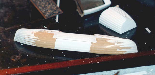
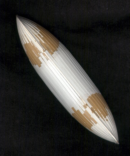
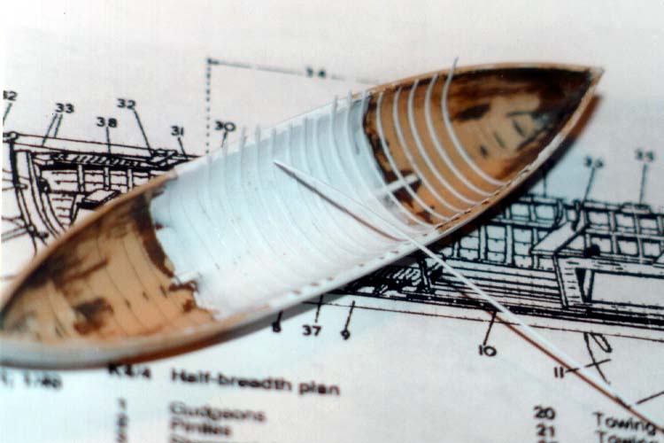
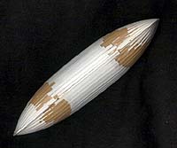 At this point I made a mistake, I should have used styrene strips to fill the gap on the outside of the hull. Instead I just used .080x.020 to plank the hull. Starting from the keel and using the kit planks as a guide I placed nine planks per side slightly overlapping each one as I added the next. Once these were done I carefully faired the new planks into the existing ones.
Turning the hull over I used the ball grinding/gouging bits in the Mini-Mite to fair the inner plug to the two original pieces. With the basic hull done, it is now time to have some fun and detail the interior.
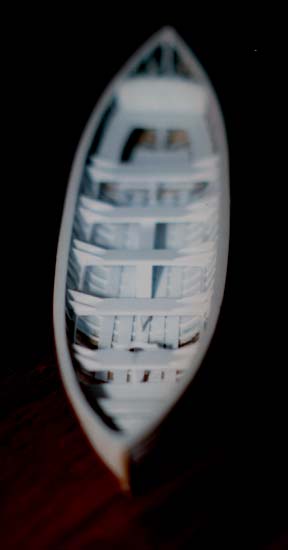
 About now I realised I had made another mistake - the cap stripl would have to be removed to allow easier installation of the frames. I carefully sliced it away with a new Exacto blade and placed it aside for later use. I began by drawing a series of vertical lines every 3mm on the inside. On these lines, .020x.010 styrene strips were glued to represent the frames. Each one was cut longer than required and given a rough curve. Testors Liquid Cement (second best model cement) was brushed on the line and it was then pressed into place using my index finger. Invariably I would have to quickly adjust its position using tweezers. After a surprisingly short time I had all the frames in place and a .020x.020 keel was added to the inside and also about 5mm from the gunnel at the midshops mark. Rather than following the rise of the bow and stern, this line was kept level fore and aft.
 Thwarts were now added from .040 styrene (too thick, next time I use .020). These sit on top of each of the stringers in the previous step. Angle pieces were cut from .060 x.010 strips and added to the edge of each thwart.
About this time I received an email from a member of my corvette mailing list about the centreboard keel and I decided I should add it. This was three pieces of styrene laminated together, leaving a slight depressiion in the centre to allow it to sit on the keel.
 | 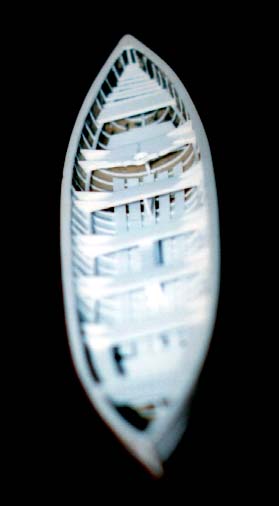 |
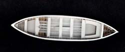
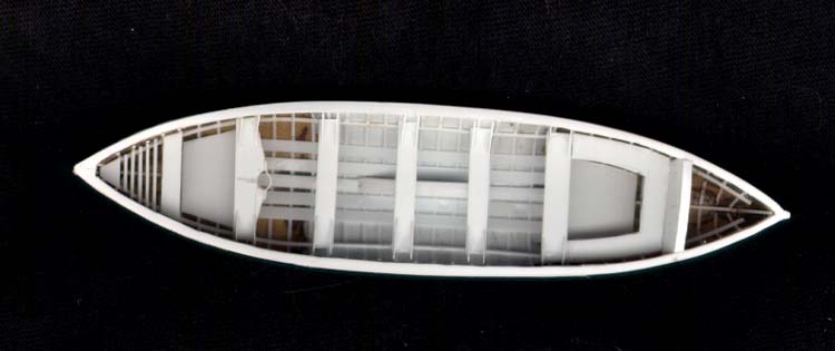
I now realised I had forgotten the floorboards. These were .080 strips placed either side of the centreboard with slight gaps between each one. A solid floor was added to the bow sheets and stern sheets. These should really be wooden grills, but I have yet to reach that level of AMS. The rear bench and bulkhead were added as were the bow slats and vertical supports under each thwart on the centreline. The cap stripwas also glued back in place.
The final construction phase was the decking over the stern and the rudder/tiller assembly. I had planned to do this with a lattice structure, which meant that there was just an opening behind the bulkhead. If I had to do it over again I would have left this as a solid structure when I cut out the interior of the cap strip. Instead I had to make a plug to fill the opening. this was then flooded with CA on the seam and sanded smooth.
The rudder was cut from .020 styrene and has .010x.020 strips wrapped around it for the two hinges. I glued each strip on one side, placed a .020 strip against the rudder and then folded the hinge stripe over this on to the opposite side. Pulling the .020x.020 strip out leaves an open loop on the rudder. Similar hinges were made on the whaler and then the rudder was joined to the hull by inserting a .010x.010 strip into the corresponding loops. These were then affixed with CA and trimmed to size.
The rudder control horn was a piece of .060x.020 strip cut to shape and glued to the top of the rudder. A second piece was glued to the top of a section of the brown rod supplied in the kit and affixed to the front of the rear decking. To the front of this a .020 x .020 section was CAed to this as the tiller itself. The whaler is basically done now.
Oh yes. .. did I say AMS has yet to strike? Earlier, while waiting for something to cure, I drilled a series of #74 holes into .010 x .060 strip. Using a new exacto blade as a guillotine I then cut as close to each of these holes as possible, leaving a tiny eyebolt. These will be used to hold the rope that goes around the outside of the hull.
Next up – the short focsle conversion !!!!!!


![]()


