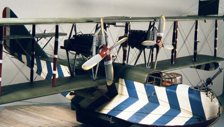
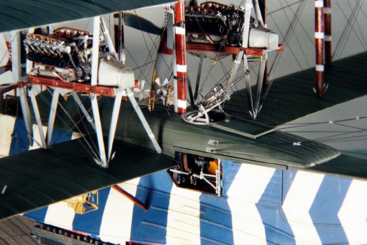
Superdetailing Lone Star Models' 1/48 Felixstowe F.2A |  | PART 2 Engines  Because the twin Rolls Royce Eagle VIIIs are very visible - completely exposed - I determined that they would be properly attended to, with all the components and the appropriate wires and control runs. The basics are provided, though much simplified, and are in scale. I find this preferable to a molded engine where one has to remove the sub-par details before super-detailing can begin. Because the twin Rolls Royce Eagle VIIIs are very visible - completely exposed - I determined that they would be properly attended to, with all the components and the appropriate wires and control runs. The basics are provided, though much simplified, and are in scale. I find this preferable to a molded engine where one has to remove the sub-par details before super-detailing can begin.  The first act was the creation of the engine bearers, and I found an excellent means of simulating routed wood by using Plastruct C-channel and in-filling where the center has not been routed out. The depressions are made to look smooth and rounded by flooding with thinned-out filler, and the results are most gratifying as well as easy to obtain. Getting the engines to perch on the bearers meant creating the appropriate supports. I used brass, epoxied to the white metal crankcase. These demonstrated an annoying tendency to part company, though epoxy is usually the best way to go. The first act was the creation of the engine bearers, and I found an excellent means of simulating routed wood by using Plastruct C-channel and in-filling where the center has not been routed out. The depressions are made to look smooth and rounded by flooding with thinned-out filler, and the results are most gratifying as well as easy to obtain. Getting the engines to perch on the bearers meant creating the appropriate supports. I used brass, epoxied to the white metal crankcase. These demonstrated an annoying tendency to part company, though epoxy is usually the best way to go.  I delayed the detailing of these engines as long as possible, as Fotocut was preparing a couple of specialty sheets of etched pieces, and a large number of Rolls Royce fiddly-bits were designed into the sheets. But Fotocut had equipment problems, and as the months dragged on without progress, I despaired and began to scratch-build the engine details. I delayed the detailing of these engines as long as possible, as Fotocut was preparing a couple of specialty sheets of etched pieces, and a large number of Rolls Royce fiddly-bits were designed into the sheets. But Fotocut had equipment problems, and as the months dragged on without progress, I despaired and began to scratch-build the engine details. One of the fundamental design decisions I made was to pre-paint (or use prototypical metals) and add the bits as I went along, rather than try to paint the entire engine after all the details were added. Using tiny brass and copper tubes, the various piping was created and glued (or soldered) together. The magneto faces were plastic, while the oil scavenger and water pumps were turned brass items. There were three particularly tricky areas: First, the intake manifolds between the Vees of the engine needed to be created from scratch, as they weren't provided. Since there are eight of these, and they need to be in identical (but handed) sets of four, the expedient way to produce them was to solder together a brass master that could be flipped over to serve in either direction. From this were created two molds, and a suitable number of resin manifolds were cast . Cleaning up the tiny resin castings was a chore, as the fragile resin decides to disintegrate only when one is almost finished.  The second area of devilment came from the overhead water pipes, four assemblies consisting of a header and six feeder tubes. Too complex to cast, these needed to be individually soldered together from .4 mm copper tube. I pressed a length of copper tube against a jig to create the distinctive angled header pipe, and get four that were (almost) identical. A second small jig was made to hold the six feeder pipes parallel so they could be soldered to the main. Even with resistance soldering equipment that keeps the heat as localized as possible, this is a tricky soldering proposition that more than taxed my prowess in miniature metalwork. The second area of devilment came from the overhead water pipes, four assemblies consisting of a header and six feeder tubes. Too complex to cast, these needed to be individually soldered together from .4 mm copper tube. I pressed a length of copper tube against a jig to create the distinctive angled header pipe, and get four that were (almost) identical. A second small jig was made to hold the six feeder pipes parallel so they could be soldered to the main. Even with resistance soldering equipment that keeps the heat as localized as possible, this is a tricky soldering proposition that more than taxed my prowess in miniature metalwork.  The third area of complication was cleaning up the exhaust pipes and attaching them tidily to the cylinders. N.4541 had shortened exhausts, and so the nicely cast pipes were chopped, and a replacement tubular end fitted to represent a hollow pipe. The cylinders were drilled, and the exhausts were married to plastic gaskets (HO railroad lifting eyes), and the whole epoxied together. The third area of complication was cleaning up the exhaust pipes and attaching them tidily to the cylinders. N.4541 had shortened exhausts, and so the nicely cast pipes were chopped, and a replacement tubular end fitted to represent a hollow pipe. The cylinders were drilled, and the exhausts were married to plastic gaskets (HO railroad lifting eyes), and the whole epoxied together. Otherwise, the details were made with suitable sheets, tubes and rods of aluminum, copper, and brass, along with the odd bit of micro-solder, styrene, and lead foil. Valve springs and plug leads were fabricated from fine steel wire. Using these materials is most gratifying, as the engine gradually emerges, piece by piece, and is not dependent on the final painting to achieve verisimilitude. In the end, each engine had about 350 pieces, and was still a much-simplified representation. Propellers  Mercifully, the handed props that came with the kit matched the length specified for AB 665, and saved me the labor of carving handed four-bladers to match, which might have exceeded whittling skills. I polished up these white metal items and filled the minor pitting with a coat of thinned putty. I resolved to represent fabric-covered blades with brass tips, all of which was accomplished with paint. A handy marking jig made sure that the brass tips were symmetrical. The brass screw heads were simulated by spotting them in white with a fine brush, then lightly over-spraying the tips with brass Metallizer. The thrust plates were photoetched items, dressed up with Copper State Models nuts and bolts, lightly weathered. Mercifully, the handed props that came with the kit matched the length specified for AB 665, and saved me the labor of carving handed four-bladers to match, which might have exceeded whittling skills. I polished up these white metal items and filled the minor pitting with a coat of thinned putty. I resolved to represent fabric-covered blades with brass tips, all of which was accomplished with paint. A handy marking jig made sure that the brass tips were symmetrical. The brass screw heads were simulated by spotting them in white with a fine brush, then lightly over-spraying the tips with brass Metallizer. The thrust plates were photoetched items, dressed up with Copper State Models nuts and bolts, lightly weathered. Machine Guns  I opted for an armament configuration that included five Lewis guns; a tandem mount on the bow Scarff ring, a single on the dorsal Scarff ring, and one in each of the doors. I had laid in a suitable supply of both Copper State Models and Fotocut Fotokit guns and addressed myself to the construction. I opted for an armament configuration that included five Lewis guns; a tandem mount on the bow Scarff ring, a single on the dorsal Scarff ring, and one in each of the doors. I had laid in a suitable supply of both Copper State Models and Fotocut Fotokit guns and addressed myself to the construction. For the Scarff rings, the kit-supplied brass would have been a good start, but I had the makings with leftover Fotocut sets, and used these. The first order of business was a jig to hold the assemblies during construction, and a suitably-sized hole in a piece of plastic stood in for the hull apertures where the rings would eventually fit. A circle of plastic served as the base, into which was fitted the flange that would drop into the hull openings and align the finished ring. Once this was taped to the jig, construction began in earnest with the Fotocut components and a .019 inch brass rod, bent to the appropriate shape to fit the elevating quadrants. Additionally, extra bits of brass, plastic, and wire supplied the details that Fotocut had simplified, all based on the drawings in the indispensable Early Aircraft Armament by Harry Woodman. Additional drawings and photographs in the Mini Datafile on Lewis guns were also useful.  There are subtle differences between the two rings. The bow emplacement has the Sandow cord in the unstretched state (much easier to model, and a stronger assembly, to boot). The dorsal ring needed modification to allow the sliding hatch cover to close, and was additionally fitted with a back rest. The Sandow cord here was tensioned over the pulleys. There are subtle differences between the two rings. The bow emplacement has the Sandow cord in the unstretched state (much easier to model, and a stronger assembly, to boot). The dorsal ring needed modification to allow the sliding hatch cover to close, and was additionally fitted with a back rest. The Sandow cord here was tensioned over the pulleys. The beam mounts are identical (well, handed for port and starboard) and are primarily made from various gauges of brass tube. Again, a small alignment fixture was concocted by scraping out a deep enough trench in plastic card to receive the lengths of brass. The pain and suffering of getting these components to stick with liquid CA glue has driven me to micro-soldering. All the various gun mounts were primed and then painted with the chosen battleship gray, and set aside to await their eventual wedding to a machine gun. I made up a Lewis gun using the Fotocut components along with a copper tube barrel (.016 inch OD) and a brass tube gas cylinder (.018 OD). To this I added a few extra details, mostly in plastic, and noted that the build time was over 10 hours. I built the second gun from the CSM kit, replacing the barrel and gas cylinder with the same diameter tube as the Fotocut effort. I managed to cut the construction time down to 3.5 hours, and had a more representative product at the end, though drilling out the trigger guard seemed a lot more difficult than it should have. Naturally, I concluded that the very best Lewis gun would be a combination, using parts from both kits and thereby doubling the cost. In the end, I created RNAS Pattern Mark IIs with slight differences in sights and muzzle details as might be reflected on an operational boat. These fit into the various mounts with small brass pins, and so would have been traversable, had I the guts to leave them operational; I didn't and superglued them to the mounts. The guns were sprayed with a blue/black enamel and lightly dry-brushed with aluminum and rubbed with graphite powder to create a "blued" finish. Windscreen/Canopy  After the hull modifications, the kit-provided pilots' greenhouse was too narrow, besides being of an atypical shape and thick to boot. I laminated up some .060 plastic to create a buck from which to vacuform a replacement. I whittled the base down so it fit properly over the cockpit, then added sheet plastic over the basic shape to create the appropriate planes where the glass/perspex would be. Satisfied with the accuracy of the shape, I hauled out my trusty Mattel vacuform machine and proceeded to melt every piece of clear styrene or acetate in the house. Eventually I succeeded in producing a suitably clear canopy, which I polished and buffed to a high sheen. After the hull modifications, the kit-provided pilots' greenhouse was too narrow, besides being of an atypical shape and thick to boot. I laminated up some .060 plastic to create a buck from which to vacuform a replacement. I whittled the base down so it fit properly over the cockpit, then added sheet plastic over the basic shape to create the appropriate planes where the glass/perspex would be. Satisfied with the accuracy of the shape, I hauled out my trusty Mattel vacuform machine and proceeded to melt every piece of clear styrene or acetate in the house. Eventually I succeeded in producing a suitably clear canopy, which I polished and buffed to a high sheen. The appropriate muntins were installed on the exterior side using slivers of NIVO-colored decals. Work then moved to the interior, wherein the muntins were created with prepainted plastic strips to emulate the more substantial wooden frames. This work is fraught with peril, as glue-smears on the interior glazing are difficult to correct, and the holding power of the necessary white glue is minimal. I also took the opportunity to cut out and thereby open up the moveable vent portions of the glass, adding an additional element of excitement to the process. The clear side panels were made up in the same way, and the whole set aside until they were eventually joined to the boat at the end of the project. Bombs/Racks/Bombsight  Needing 230 pound bombs, I had no alternative but to turn one using a lathe. Once the basic shape (sans fins) was achieved, I added what little surface detail was needed and cast a couple out of resin. The castings were slotted for the fins, which were made up of .010 inch plastic sheet. I made a jig to build the appropriate racks out of plastic shapes, then mounted and wired the bombs. I carefully painted them an appropriate mustard-buff shade and added representative markings and stripes from decal. After final weathering, they were ready to be added to the assembly, and promptly disappeared under the wings. Needing 230 pound bombs, I had no alternative but to turn one using a lathe. Once the basic shape (sans fins) was achieved, I added what little surface detail was needed and cast a couple out of resin. The castings were slotted for the fins, which were made up of .010 inch plastic sheet. I made a jig to build the appropriate racks out of plastic shapes, then mounted and wired the bombs. I carefully painted them an appropriate mustard-buff shade and added representative markings and stripes from decal. After final weathering, they were ready to be added to the assembly, and promptly disappeared under the wings.  One alarming adventure along the way; one of the bombs, duly detailed and painted, began decomposing some months after it was completed. The resin oozed through the paint and decals, and rotted the styrene details. I presume this was the result of a poor mix of resin, but the fact that there was never a hint of a problem for several months is disconcerting. I scrapped the bomb and made another, still wondering what went awry. One alarming adventure along the way; one of the bombs, duly detailed and painted, began decomposing some months after it was completed. The resin oozed through the paint and decals, and rotted the styrene details. I presume this was the result of a poor mix of resin, but the fact that there was never a hint of a problem for several months is disconcerting. I scrapped the bomb and made another, still wondering what went awry.  The Mark II Low-Height bombsight would be prominent in the bow of the boat, and I spared no effort to concoct a representative example. Starting with the Fotocut CFS sight from the ''Parts Extravaganza'', I modified the brass elements to create the later version commonly seen on the operational boats, and dolled it up with slivers of plastic and scrap brass. This was "blued" in the same manner as the Lewis guns - blue/black enamel paint - and then final brass details were added with wire. The Mark II Low-Height bombsight would be prominent in the bow of the boat, and I spared no effort to concoct a representative example. Starting with the Fotocut CFS sight from the ''Parts Extravaganza'', I modified the brass elements to create the later version commonly seen on the operational boats, and dolled it up with slivers of plastic and scrap brass. This was "blued" in the same manner as the Lewis guns - blue/black enamel paint - and then final brass details were added with wire. Wing Assembly  I set up my wing jig to accept the boat, and noted that it wasn't big enough to accommodate the model on its trolley/cradle. Nevertheless, the jig is a handy place to set the model, as the leading edge stops can be used to square the assembly and the jig serves as a protective holder while the model is manhandled. I set up my wing jig to accept the boat, and noted that it wasn't big enough to accommodate the model on its trolley/cradle. Nevertheless, the jig is a handy place to set the model, as the leading edge stops can be used to square the assembly and the jig serves as a protective holder while the model is manhandled.  I slipped the wings onto the spar stubs and confirmed the alignment, then cemented them in place with slow-setting epoxy. The underwing struts with their long pins provided the crucial bracing that prevented the long lower wings from sagging. With everything trued up, I resisted the temptation to fiddle with it and left it overnight to set up hard. I slipped the wings onto the spar stubs and confirmed the alignment, then cemented them in place with slow-setting epoxy. The underwing struts with their long pins provided the crucial bracing that prevented the long lower wings from sagging. With everything trued up, I resisted the temptation to fiddle with it and left it overnight to set up hard.  I had determined very early in the project that the music-wire struts and wood-core wings would provide enough tight connections to obviate the need for gluing any of these parts, a startling departure for a plastic modeler. But the use of functional rigging, glued to both wings, would serve to hold the model together without the struts being glued to either wing - and so it proved. I had determined very early in the project that the music-wire struts and wood-core wings would provide enough tight connections to obviate the need for gluing any of these parts, a startling departure for a plastic modeler. But the use of functional rigging, glued to both wings, would serve to hold the model together without the struts being glued to either wing - and so it proved. The top wing was the soul of simplicity, though to hear me swearing you'd have thought the process was difficult. Without glue, there was no time limit, and I stuck the struts into the to wing and worked my way outward from the fuselage, adding a couple of strips of masking tape to keep the top wing from popping off. In the course of the action, I managed to knock off the pitot cable, the tow rings fore and aft, the port aileron, and pulled up two rib-tapes - about par for the course. I should know by now that separated ailerons need to be pinned and epoxied to the wing, and to not rely on CA glue. Ailerons and rudders cut to be off-set need a more robust fastening system, as they are inevitably bumped along the way, or pulled loose in the rigging process. Very late in the project, I drilled the control surfaces for pins and epoxied them in place! and it would have been a lot easier before these parts were painted and attached to the model.  Once the top wing was on, I started the rigging, working in from the outside, but leaving the engine cellules loose to accommodate that addition. With the outer three bays done on both sides, the model could be inverted without fear of losing the wing, but it was still a considerable handful, and the mortal dread of actually dropping it ensured that I paid close attention. Once the top wing was on, I started the rigging, working in from the outside, but leaving the engine cellules loose to accommodate that addition. With the outer three bays done on both sides, the model could be inverted without fear of losing the wing, but it was still a considerable handful, and the mortal dread of actually dropping it ensured that I paid close attention. Rigging  My favorite monfilament 'invisible thread' was used, but this time with some new (for me) twists. First of all, the thread was wrapped around some foam-core to stretch it suitably. At the same time, it was pre-colored with indelible markers. I determined, about midway through the project, that it is not necessary to drill all the way through the top wing. Drilling halfway from the underside, and setting the thread with gel CA avoids a lot of tedious topside repairs. These thread lengths were taped up to the undersurface of the top wing to keep them out of the way, and it worked out fine. Likewise, rigging runs that emanated from the fuselage were secured internally, and taped out of the way until needed. My favorite monfilament 'invisible thread' was used, but this time with some new (for me) twists. First of all, the thread was wrapped around some foam-core to stretch it suitably. At the same time, it was pre-colored with indelible markers. I determined, about midway through the project, that it is not necessary to drill all the way through the top wing. Drilling halfway from the underside, and setting the thread with gel CA avoids a lot of tedious topside repairs. These thread lengths were taped up to the undersurface of the top wing to keep them out of the way, and it worked out fine. Likewise, rigging runs that emanated from the fuselage were secured internally, and taped out of the way until needed.  Another new method was to locate the bottom-wing rigging holes with a prick-punch, and drill them out with a .008 guitar string chucked into the mototool. There is no reason to do this until the wing is completely finished, as weathering coats and sealers re-clog the hole. These have to be repaired, but the fact that they are on the bottom wing undersurface mitigates the damage. The other thing to bear in mind while drilling these holes is that the appropriate struts and other wing fittings should already be in place, at least temporarily. Their presence encourages the 'drill bit' to seek its path elsewhere, and one is not confronted with (too many) filled-up rigging holes when the time comes to feed the rigging through. When, as inevitably happens, one encounters a hole that has scarred over, hand manipulation with a piece of wire will renew the passage. Another new method was to locate the bottom-wing rigging holes with a prick-punch, and drill them out with a .008 guitar string chucked into the mototool. There is no reason to do this until the wing is completely finished, as weathering coats and sealers re-clog the hole. These have to be repaired, but the fact that they are on the bottom wing undersurface mitigates the damage. The other thing to bear in mind while drilling these holes is that the appropriate struts and other wing fittings should already be in place, at least temporarily. Their presence encourages the 'drill bit' to seek its path elsewhere, and one is not confronted with (too many) filled-up rigging holes when the time comes to feed the rigging through. When, as inevitably happens, one encounters a hole that has scarred over, hand manipulation with a piece of wire will renew the passage. Finally, I used different sized monofilament strands for different applications, As I have learned in the past, the final trimming did not take place until the model was largely complete; a one-inch pigtail leaves the modeler with a place to grip, and re-pull a run of rigging that goes slack if damaged in further finish construction. Turnbuckles were painted on with thinned body putty, a technique upon which I have yet to find improvement. I would love to incorporate more detail on these, but I'm damned if I'm going to hand-tie them. Final Assembly  Because the metal engines were quite heavy, I never wanted to invert the boat once they had been installed, and that meant a departure from the typical order of assembly. With the knowledge that I would need to complete all the rest of the work from the topside only, very careful planning was crucial. Here is the approach: Because the metal engines were quite heavy, I never wanted to invert the boat once they had been installed, and that meant a departure from the typical order of assembly. With the knowledge that I would need to complete all the rest of the work from the topside only, very careful planning was crucial. Here is the approach: With almost all rigging done, the plane was inverted for the last time to attach the bombs, wing floats, and clean up the rigging that protruded from the underside of the bottom wings. At the same time, the complicated fuel line arrangement was secured to the center section of the upper wing, as were the aileron controls on the underside of the wing. The model was returned (permanently, I fervently hope) to an upright position. Once the oil tanks and their pipes were mated to the engine bearer assembly, these structures were added between the wings. The 45-degree side bracing was slipped in to tie the vee struts to the fuselage, and the various engine control runs were added. The aft inverted vee-struts were cemented in place over the oil tanks, and trimmed to mate with the engine bearers and the top wing. The completed engine was slid onto its bearers from the front of the plane, mating to the oil connections from those tanks. The gasoline feeds, from the overhead gravity tank, traveled down the inverted vee struts to the rear of each engine. The front inverted-vee struts were added and trimmed to fit. The completed radiator assemblies were slipped onto the engines from front, mating to the water connections from engine. The upper wing stabilizers were added and rigged, along with the topside aileron control runs. The tail assembly was added, along with its struts, and the tail control lines were connected. The greenhouse canopy was secured with white glue. The large anti-drag stays were connected from the wing undersides to the bow of the boat. The final delicate details – machine guns and bombsight – were added with white glue. The author had several drinks at a safe distance from the project. The project consumed 747 hours over a period of 18 months from October, 2000 to March, 2002. As with any vacuform, the modeler needs to supply most of the details from scratch, but the possibility of a 1/48 injection-molded Felixstowe seems pretty remote, and I don't fancy those long wings in resin. Assuming I ever make another biplane, it is going to be something a lot simpler! but I'm sure grateful to Lone Star Models for having the guts to produce a kit this ambitious. References: -
WWI Aero109, 134, 135, 159, 165, 166, 167 -
Cross and Cockade 4/1, 9/1, 9/2, 11/1 -
Cross &Cockade International 19/3, 21/4, 24/1, 28/4, 29/2, 29/3 -
Over the Front 5/2, 9/2 -
Scale Models December, 1977 -
Albatros Productions
Windsock International 7/2, 6/5, 14/1, 17/2, 17/3
Felixstowe Datafile 82, by J.M. Bruce
FE2b Datafile 18, by J.M. Bruce
DH4 Datafile Special Volume 1, by J.M. Bruce
British Aeroplane Colours - Fabric Special 2, by Bruce Robertson
British WWI Aeroplane Propellers, by Peter Cooksley -
Lewis Guns - Mini Datafile 3, by Harry Woodman -
MAP Plan Pack Felixstowe F2A, by Rupert Moore -
Harleyford Publications Marine Aircraft of the 1914-1918 War, by Heinz Nowarra -
US Navy Department Unpacking and Assembly Handbook Felixstowe F-5-L -
US Navy Gas Engine School Construction, Materials, & Inspection of Hulls Handbook Curtiss H-16 -
Rolls Royce Official Handbook for Falcon and Eagle Engines -
Schiffer Military History US Naval Aviation , 1910-1918, by Noel Shirley -
Hikoki Publications Royal Naval Air Service, 1912-1918, by Brad King -
Collier's Encyclopedia Photographic History of the World's War -
Arms and Armour Press The Spider Web , by T.D. Hallam -
Smithsonian Institution Press Early Aircraft Armament, by Harry Woodman -
British Air Ministry Details of Aerial Bombs Return to Part 1... | 


|