Azur 1/72 CAMS 37A |  | Introduction When I was given this kit to review I thought that it shouldn't be too hard, as I seem to be building more and more limited run kits, and should be used to their shortcomings. The Kit 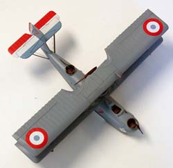 The kit comes in two medium gray sprues with a bag of resin detail parts, a clear vacu-formed sheet with two windscreens and two nose window sections. A sheet of very nice decals for one French boat stationed in Saigon and one for the Portuguese Marine. The instruction sheet consists of eight 6in by 8in pages with the typical exploded views. What instructions are provided, are in four languages. The colors given for the two aircraft are similar, but just a little confusing. Both have light blue gray uppers but with different F.S. numbers. No problem, except that the Czech language color guide calls both "modroseda svetla", and the interior of both is also light blue gray but named "svelte modroseda". What do you think? What's the difference between svetla and svelte? The kit comes in two medium gray sprues with a bag of resin detail parts, a clear vacu-formed sheet with two windscreens and two nose window sections. A sheet of very nice decals for one French boat stationed in Saigon and one for the Portuguese Marine. The instruction sheet consists of eight 6in by 8in pages with the typical exploded views. What instructions are provided, are in four languages. The colors given for the two aircraft are similar, but just a little confusing. Both have light blue gray uppers but with different F.S. numbers. No problem, except that the Czech language color guide calls both "modroseda svetla", and the interior of both is also light blue gray but named "svelte modroseda". What do you think? What's the difference between svetla and svelte? On to the plastic. The interior is all resin, floor, seats and instrument panel. The upper wing comes as top and lower halves. The lower wing has a two-part center section with solid outboard panels. Fortunately the trailing edges of the sections are not as thick as the wings on other Azur kits. The panel lines on the wings are very fine but clean and crisp. There are no panel lines on the hull and I think it means that the hull was molded plywood. There are no locating pins or tabs but there are small pinpricks where the many struts are located. The engine is a five part casting with three banks of cylinders! Also included is the option to make the amphibian that was furnished to the Portuguese, but was not widely used.  There is very little flash on the moldings and clean up was been easy and part fit is very good. With all the small struts that are required it's nice to have the upper and lower halves of the molds in register. The only disappointment was the front and rear gun mounts – there aren't any. They are of the rotating ring and pivoting raised bar type and are very prominent. This is one time I would like to have an etched brass set to go with a model. [EDITOR'S NOTE: Most of the WWI aftermarket companies sell PE Scarff mounts of the type described above - RNP] There is very little flash on the moldings and clean up was been easy and part fit is very good. With all the small struts that are required it's nice to have the upper and lower halves of the molds in register. The only disappointment was the front and rear gun mounts – there aren't any. They are of the rotating ring and pivoting raised bar type and are very prominent. This is one time I would like to have an etched brass set to go with a model. [EDITOR'S NOTE: Most of the WWI aftermarket companies sell PE Scarff mounts of the type described above - RNP]
Assembly After sanding down the trailing edges of each half of the upper wing to thin out the trailing edge, the two halves were glued together. I then taped the body halves together and test fit the cockpit floor for fit. It didn't. The resin floor is .10 thou. smaller than the inside of the body. 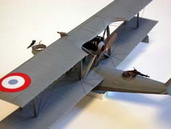 I know this is a limited run kit, but that's a lot of mismatch even for a kit maker, and with no locating tabs or any other way to figure out where the floor goes, it's rather hard to locate. My initial feeling is that the kit instructions leave a lot to chance. After building up the floor with sheet styrene I was able to fit it inside the body thru the opening for the lower wing. I know this is a limited run kit, but that's a lot of mismatch even for a kit maker, and with no locating tabs or any other way to figure out where the floor goes, it's rather hard to locate. My initial feeling is that the kit instructions leave a lot to chance. After building up the floor with sheet styrene I was able to fit it inside the body thru the opening for the lower wing.
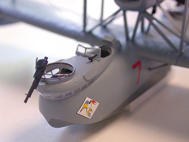
The aft gunner's floor was an easy fit as I just pushed it in as far as it would go and glued one side to the hull with super glue. After both decks had been stuck to one side of the body, I removed the tape holding the two sides together and painted the interior. As soon as the paint dried, the two sides were glued together. Next the lower wing was assembled. This showed up another problem, as the center section of the lower wing is thicker than the outboard panels. There isn't much that I could do about it once the center section had been glued together. The outer panels have a dihedral of about four-and-a-half degrees. Since the sections are a butt join with no tabs, the mating edges are suspect. I had to tape the center section to the work surface and block the tips until they measured the same. This could get me in trouble mounting the upper wing as it's straight and all those struts may not fit. After mounting the lower wing to the hull (a good fit), and filling and sanding down the seam, it was time to fit the nose windows and cockpit cap. The window section is a clear vac part that looks like a horseshoe shaped wedge that is best fit to the cockpit cap for best results. The opening in the body is over sized and needs to be filled with sheet stock. With all the main body parts assembled and the lower wing in place and joints smoothed up, I fit the resin gun tubs. The nose and aft tubs are different sizes with the aft one being slightly smaller, so test fit first. I contoured the tub walls to fit the inside hull shape so it didn't look like a can. 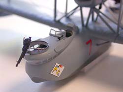 With the main hull and lower wing assembly complete, it was time to stick on some of the resin fiddly-bits that come in the kit. Two small ironing board looking parts go on the upper body between the windscreen and the gunner's tub. No location was shown on the left side so going by the three views I super glued it on. Sure enough there was an outline on the right side to show the correct location, which was not the same as the other side. With a lot of luck the left one came off without breaking. So on to the next dilemma. With the main hull and lower wing assembly complete, it was time to stick on some of the resin fiddly-bits that come in the kit. Two small ironing board looking parts go on the upper body between the windscreen and the gunner's tub. No location was shown on the left side so going by the three views I super glued it on. Sure enough there was an outline on the right side to show the correct location, which was not the same as the other side. With a lot of luck the left one came off without breaking. So on to the next dilemma. The instruction sheets show a square part mounted on the left side just ahead of the ironing board. But, none of the three views or box art (usually more correct than the instructions) shows the part. It's square with an airfoil shape. I have no clue as to what it is, and no references to work with. Moving right along, I have managed to mount the engine pod and tip floats without too much misalignment. I even painted some of the tail surfaces. That brought up another concern – paint. Every color called out needed to be custom mixed. I thought that for the sake of my health I would use acrylics. Well, after a couple of tries, and the paint lifting off with the masking tape, it was back to enamels. Cough, cough. OK, now to fit the upper wing. Since there are no alignment pins, only flat surfaces, this is going to be a real bear. I glued the two sets of inboard struts and tried to set the wing up from that. After jigging up the model so it was level, I sat the upper wing on the struts. This didn't work out to well as none of the struts seemed to be the correct height. The location of the struts influences this, but it's a guessing game as to location. Thanks to my past life as a model maker for a major aircraft company here in the northwest United States , I was able to set up the model square and level using a caliper and a scale to level things out. 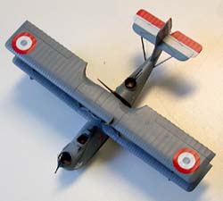 Having to place trust in part size on a limited run kit is a leap of faith, and showed that the upper wing slanted to one side by .150 thou. Using angle blocks and a square to align things, I found that new struts would be needed to get the upper wing to fit. After each pair of struts was matched to length, I glued them to the wing in a best guess location. Have you ever tried to level a chair or table by sawing off the legs? It's a lot harder when there are eight legs. Having to place trust in part size on a limited run kit is a leap of faith, and showed that the upper wing slanted to one side by .150 thou. Using angle blocks and a square to align things, I found that new struts would be needed to get the upper wing to fit. After each pair of struts was matched to length, I glued them to the wing in a best guess location. Have you ever tried to level a chair or table by sawing off the legs? It's a lot harder when there are eight legs.
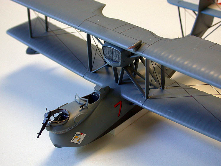
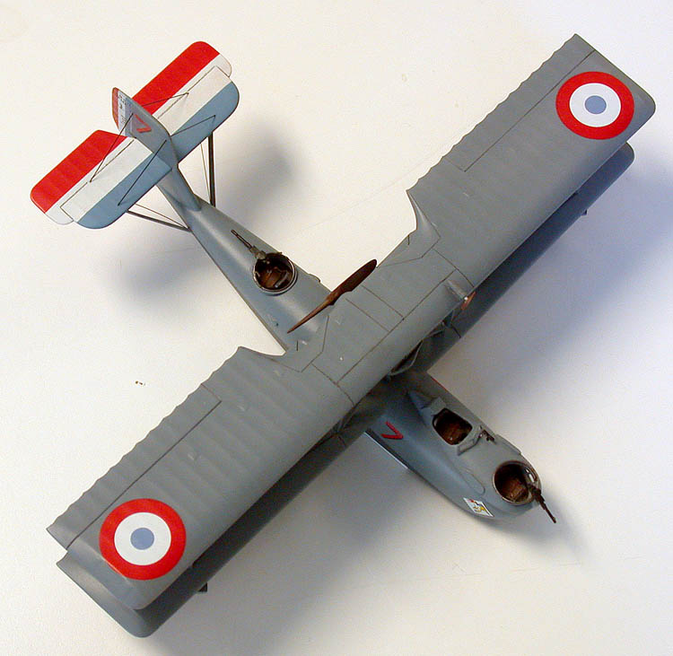
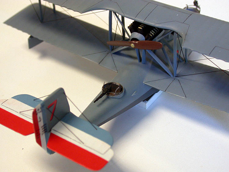
After about three days, I had the top wing level and glued on. Next came the horizontal and vertical. Both had been painted with the tri-color, so care needed to be taken with the glue joint. I forgot to mention that I had painted the hull and lower wing before attaching the upper wing. There is so much clutter around the exposed engine that there was no way to mask the engine after the top wing was mounted. After a spell of burnout, the rest of the model was painted. What with touch-ups and waiting for the paint to dry, a gloss topcoat was applied as a base for the decals.  The decals went on just fine, and after a couple of light coats of semi- gloss, cames the rigging. I only had the box art to go by, so without further ado out came the sprue for stretching. This is a tedious job, but the model would look naked without it. With all the struts and wires to induce vast amounts of drag, they must have needed vast amounts of water to get airborne with only one engine. The model is just about finished, only fiddle bits to go. Remember back when I said there were no scarff rings for the guns? Well, I cobbled a couple up out of brass wire and they only look half bad. I do not claim to be an exacting model builder; in fact I build standoff models. The farther you stand off, the better they look. The decals went on just fine, and after a couple of light coats of semi- gloss, cames the rigging. I only had the box art to go by, so without further ado out came the sprue for stretching. This is a tedious job, but the model would look naked without it. With all the struts and wires to induce vast amounts of drag, they must have needed vast amounts of water to get airborne with only one engine. The model is just about finished, only fiddle bits to go. Remember back when I said there were no scarff rings for the guns? Well, I cobbled a couple up out of brass wire and they only look half bad. I do not claim to be an exacting model builder; in fact I build standoff models. The farther you stand off, the better they look. Conclusion This kit could be made into a very nice part of a model collection if you are willing to spend the time and have reference material to work with. | 


|