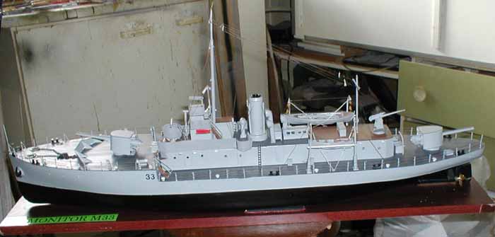
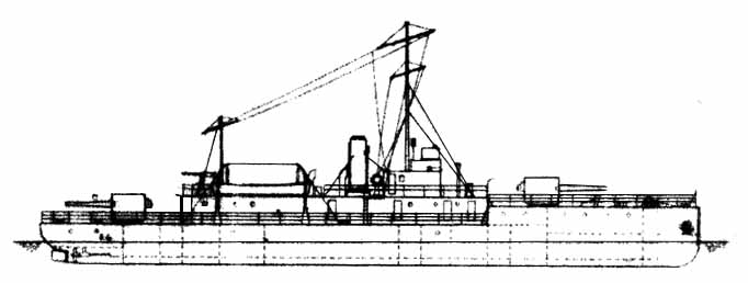
HM Monitor M33 by George Peat | 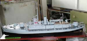 | Technical Particulars Displacement 355 tons legend, 580 deep.
Dimensions:
Length 177'-3",
Breadth 31'-0"
Draft 5'11" deep
Complement 5 officers, 67 men
Armament 2x6" single guns. 1x6pdr Hotchkiss H/A gun 2x303" Maxim guns
Protection, Hull nil, 6" gun shield 3" front
Machinery Twin screw triple expansion, 400 I.H.P. @ 250rmp
Oil fuel 45 tons, Endurance 1440 miles @ 8 knots
Speed 10 knots designed, 9 service Trials M33 9.61knots
Construction Workman Clark, Belfast 22 May 1915
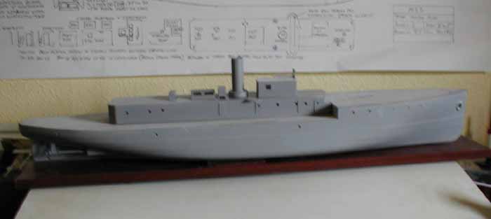
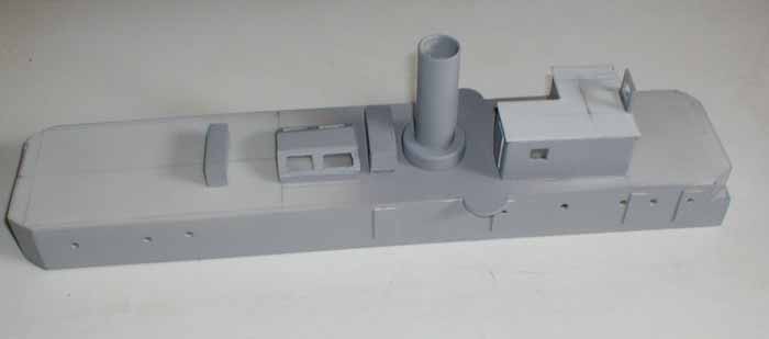
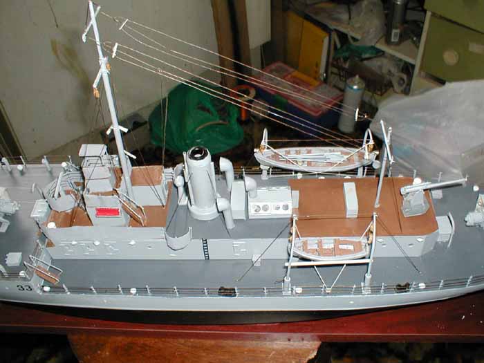
Still afloat Portsmouth and undergoing restoration by the M33 project Portsmouth The Model  The hull to a scale of 1/72nd was purchased from APS Models in Australia. The G/A drawings were obtained from the M33 project in Portsmouth and the other drawings from Dave Woolley. Both sets were to a scale of 1/96th so had to be enlarged and this was done by a local firm of copiers for a modest cost. Other reference material was obtained from the book 'Big Gun Monitors' by Ian Buxton. Photographs were obtained from the Imperial War Museum; Ulster Folk and Transport Museum of the sister ships of M33; and from Dave Wooley who had visited the ship in Portsmouth dockyard and took the detailed photographs on board. The hull to a scale of 1/72nd was purchased from APS Models in Australia. The G/A drawings were obtained from the M33 project in Portsmouth and the other drawings from Dave Woolley. Both sets were to a scale of 1/96th so had to be enlarged and this was done by a local firm of copiers for a modest cost. Other reference material was obtained from the book 'Big Gun Monitors' by Ian Buxton. Photographs were obtained from the Imperial War Museum; Ulster Folk and Transport Museum of the sister ships of M33; and from Dave Wooley who had visited the ship in Portsmouth dockyard and took the detailed photographs on board. 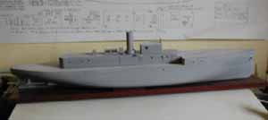 The first thing to be done is to fit the prop shafts and rudder the holes for the shafts and rudder were drilled after first marking the positions carefully taking the measurements from the drawings. To prevent any accidents at this stage these were marked on to masking tape, which was placed in the area where the holes were to be drilled. The masking tape prevents the drill from slipping while the initial holes were being drilled. The holes were then enlarged carefully with a file until the required size was obtained. The slits for the 'A' frame was drilled and enlarged to the size required. The first thing to be done is to fit the prop shafts and rudder the holes for the shafts and rudder were drilled after first marking the positions carefully taking the measurements from the drawings. To prevent any accidents at this stage these were marked on to masking tape, which was placed in the area where the holes were to be drilled. The masking tape prevents the drill from slipping while the initial holes were being drilled. The holes were then enlarged carefully with a file until the required size was obtained. The slits for the 'A' frame was drilled and enlarged to the size required. 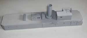 The prop tubes were cut to size and the bearings at one end tapped out and replaced to the proper length to allow for the exposed area of the shafts. The 'A' frames were made by soldering a length of tube which is a sliding fit over the prop shaft to two legs cut from brass sheet in the form of a 'V' the tube at the point of the 'V'. The whole assembly was then offered up to the hull and placed in position. The motors - 2 Mabuchi 385 types - were lined up to the shafts to ensure smooth running and cross members put into place to support them and also to provide motor mounts. The motors them selves are held in place with elastic bands over the motors and over the ends of the timber supports. [Extremely lo Tech but effective as it allows some movement in the motors to adjust themselves into final alignment as well as quick change of motors as and when required]. The 'A' frames were then positioned to allow the correct free turning of the shafts and the excess material bent over inside the hull and tacked in place with superglue. To ensure that all the holes drilled for the prop shafts, 'A' frames and rudder are watertight a two part resin mix was made and poured over the points of entry into the hull and allowed to set. The rudder is made from a small Ripmax rudder with the blade cut down to scale size and 1/4" over size at the bottom and sandwiched between plastic card with epoxy glue and clamped until it is dry then sanded to shape The prop tubes were cut to size and the bearings at one end tapped out and replaced to the proper length to allow for the exposed area of the shafts. The 'A' frames were made by soldering a length of tube which is a sliding fit over the prop shaft to two legs cut from brass sheet in the form of a 'V' the tube at the point of the 'V'. The whole assembly was then offered up to the hull and placed in position. The motors - 2 Mabuchi 385 types - were lined up to the shafts to ensure smooth running and cross members put into place to support them and also to provide motor mounts. The motors them selves are held in place with elastic bands over the motors and over the ends of the timber supports. [Extremely lo Tech but effective as it allows some movement in the motors to adjust themselves into final alignment as well as quick change of motors as and when required]. The 'A' frames were then positioned to allow the correct free turning of the shafts and the excess material bent over inside the hull and tacked in place with superglue. To ensure that all the holes drilled for the prop shafts, 'A' frames and rudder are watertight a two part resin mix was made and poured over the points of entry into the hull and allowed to set. The rudder is made from a small Ripmax rudder with the blade cut down to scale size and 1/4" over size at the bottom and sandwiched between plastic card with epoxy glue and clamped until it is dry then sanded to shape 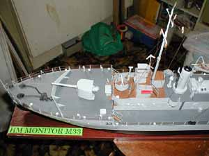 A wooden framework was built round a 6volt 4amp battery, used for power and the frame secured inside the hull . A wooden framework was built round a 6volt 4amp battery, used for power and the frame secured inside the hull . To start with the hull was framed with 1/4" ramin to support the deck and frames. This was stuck in place with a two part epoxy after first keying the inside of the GRP hull to accept the adhesive. The frame is held in place with clips [clothes pegs are ideal for this job] to hold it in place while it is drying Cross braces were then cut to size and glued into position making sure that the access area is kept free of any obstructions. The plating was represented on the hull by using 20mm wide masking tape and after painting the first layer of the complete hull the masking tape was the applied in alternative rows and then the exposed parts are given another coat of paint. A second coat of paint is given after the first one is dry and when this is dry the tape is carefully removed and you have the plating on the hull, all that remains to be done then is to scribe the individual plates on to the surface with a sharp point Anchor cable pipe holes are drilled out and brass tube of the required diameter fitted into position. Using body filler to ensure that the joint is watertight fills the inside of the hull. The scuttle positions are marked and drilled out, then after all hull painting is complete 3mm acrylic clear rod is inserted to glaze the scuttles. There are no eyebrows fitted to the scuttles. 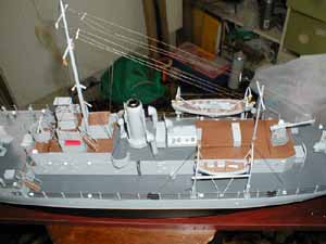 The main deck and the forecastle deck are cut from 2mm thick plastic card and the plating represented by white vinyl strips cut to the correct length & width and laid in position overlapping where the plates overlap on the full size ship and rubbed down with a soft cloth. The larger supporting plates for the 6" guns are then cut and placed in position and rubbed down with a soft cloth to secure them The pivot position for the two main guns is then marked and drilled out to allow for the guns to rotate if required. A coaming is then cut from plastic card allowing the superstructure to fit securely over and provide a watertight joint and trimmed to fit round the deck opening and stuck down. The basic hull and deck are now complete apart from the painting. The main deck and the forecastle deck are cut from 2mm thick plastic card and the plating represented by white vinyl strips cut to the correct length & width and laid in position overlapping where the plates overlap on the full size ship and rubbed down with a soft cloth. The larger supporting plates for the 6" guns are then cut and placed in position and rubbed down with a soft cloth to secure them The pivot position for the two main guns is then marked and drilled out to allow for the guns to rotate if required. A coaming is then cut from plastic card allowing the superstructure to fit securely over and provide a watertight joint and trimmed to fit round the deck opening and stuck down. The basic hull and deck are now complete apart from the painting. The superstructure and upper deck are marked out on 2mm plastic card and the deck cut out. The centre line is marked on the deck to ensure that everything is correctly placed as required. The superstructure sides And rear has the porthole positions marked out and drilled before joining together with the upper deck. Doors are cut and stuck into position with hinge details and handles being fitted after the doors are in place. The funnel is cut from 20mm diameter plastic tube and a hole cut through the deck to accept the funnel. The base of the funnel is cut from a 35mm film canister and carefully cut out to fit over the funnel 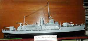 The hull and superstructure are painted in Humbrol M 127 [Ghost Grey] The steel decking is painted using Humbrol M 123 and the area's covered by cortecene are painted light brown. The hull and superstructure are painted in Humbrol M 127 [Ghost Grey] The steel decking is painted using Humbrol M 123 and the area's covered by cortecene are painted light brown. Deck Rails are from brass wire cut to length and super glued into pre-drilled holes with black thread forming the actual guard lines. The canvas dodgers are simply toilet paper sprayed grey and placed in position. The masts are cut from aluminium tubing and inserted into the pre-drilled holes in the superstructure decking with the rigging fitted. The various ventilators required, ships boats davits and the anchor winch were bought from Sirmar, painted and fitted. The ships boats were bought from Quay craft with oars and rudder made from plastic rod & plastic card. | 


|