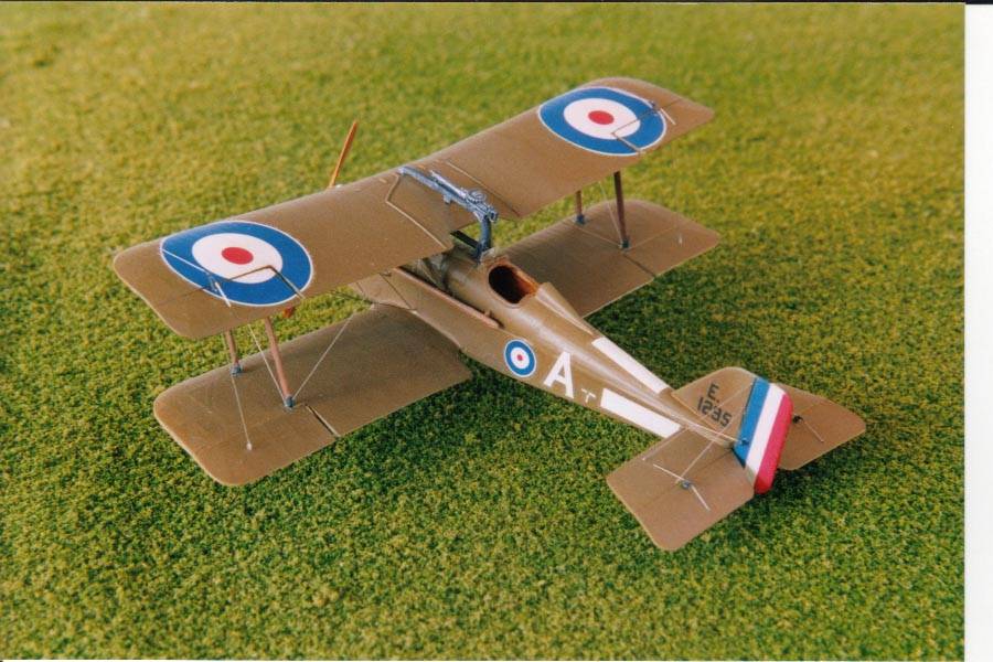
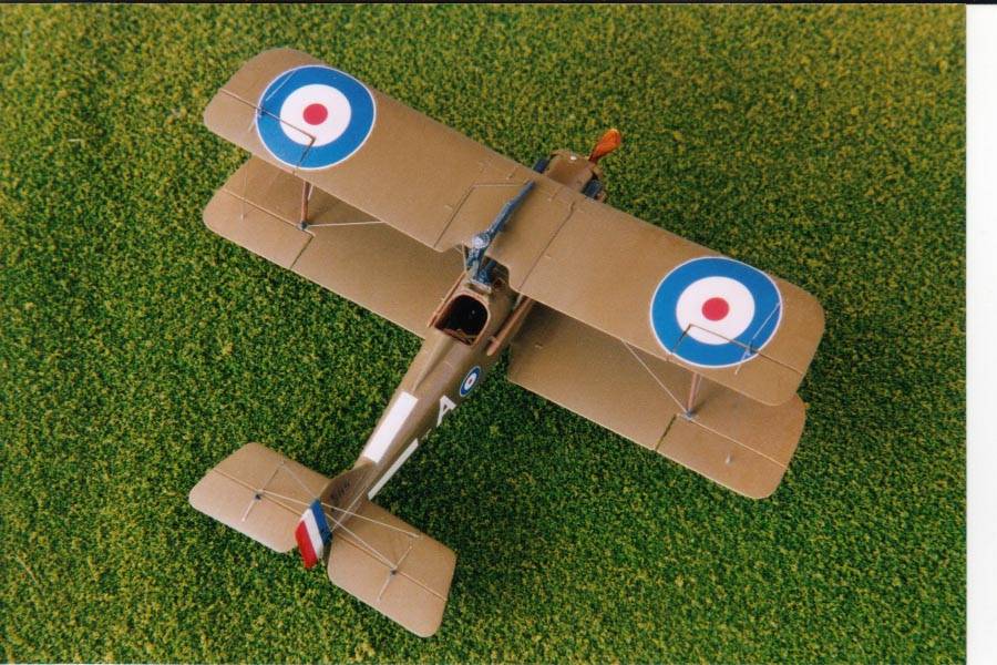
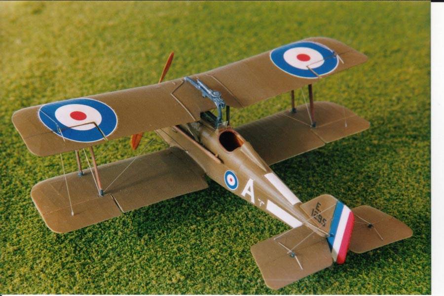
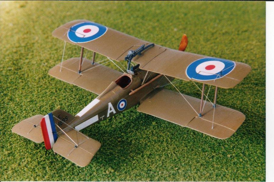
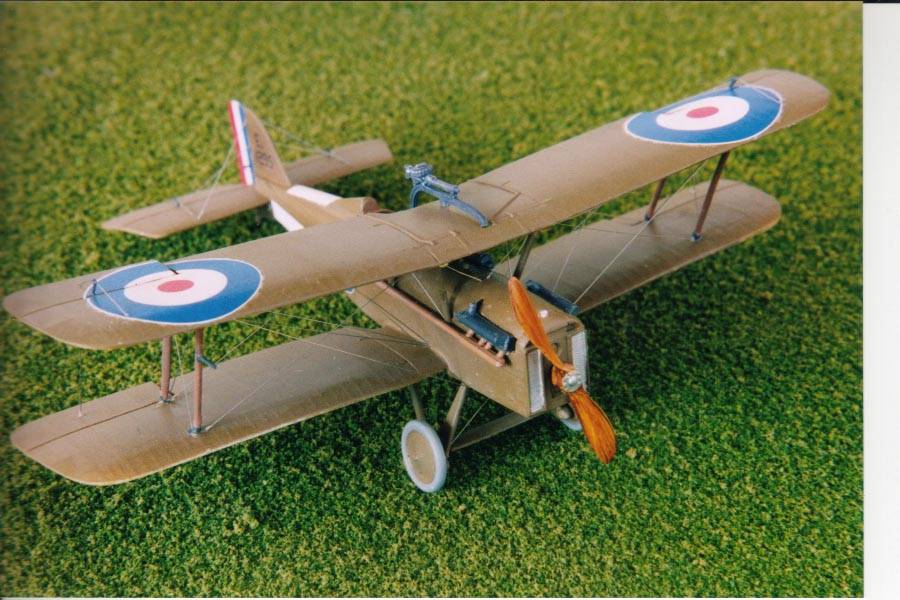
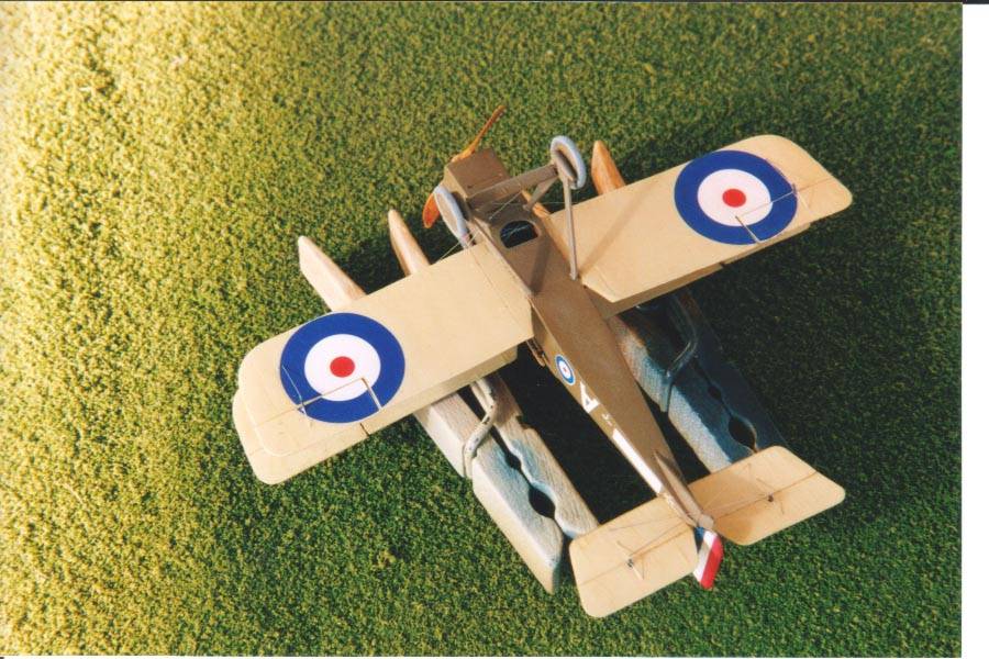
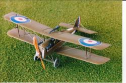
Roden's 1/72nd Scale R.A.F. SE5a Wolsey Viper Version |  | History An in-box review of this kit appeared in an earlier edition of Internet Modeler so I will not give a detailed description of the kit's contents. In brief, the kit comprises three sprues of grey plastic, a clear acetate sheet to make the clear parts and a decal sheet for four Royal Air Force schemes, al of which are variations on the PC-10 (green-brown) upper with clear doped linen (CDL) undersides. The Royal Aircraft Factory, Scout Experimental 5a or RAF SE5a, was built using the 200-hp Hispano-Suiza or Wolsey Viper engine: this kit provides for the latter. Not without its problems, by October 1918, virtually every Royal Air Force squadron in France contained the SE5a. According to J. M. Bruce, the SE5a was one of the greatest aeroplanes of its time as demonstrated by the success of its pilots. Mick Mannock, whose scheme I chose for this model, was the highest scoring British pilot in World War One. Cockpit and fuselage interior  As usual I began with the cockpit components. The kit provided a piece (18A) that represents the "shelf" surrounding the sides of the fuselage, which I thought did not go round far enough, so I made a new one with longer ends that wrapped further along the interior sides. I was somewhat puzzled about the little disk-shaped piece (10A) that is supposed to go into the instrument panel: I left it off because my references did not show anything like that, or at least, I could not see anything. I added "Instruments" to the instrument panel using Harry Woodman's method of cutting small cross sections of different sized plastic rod and gluing to the kit part. Not too much detail was required because the instrument panel sits far forward and one can barely see it once the fuselage halves are glued. The good thing here is that the kit has a separate piece (6A) for the fuselage decking and you can play around with the instrument panel without having to constantly dry-fit to see if the fuselage halves will close properly. I sprayed the fuselage interior with Aged White and coloured in the kit's interior framework with a brown pencil. Rather than glue the foot rudder and control stick into the fuselage floor as per the instructions, I made a faux-wood floor: this floor piece also hid the centre seam, which would have been visible had you looked down from above into the fuselage. I made the floor by spraying a piece of 0.020-inch plastic card with acrylic "Wood", then I applied gouache water colour paint - mainly burnt umber and dark brown - using a Q-tip, to make streaks. I then sprayed Tamiya Clear Yellow sealed with a coat of brushed Future. To save effort and time, I also applied the same process to the kit's propeller. I added seatbelts made from a champagne bottle's foil. I also made some instruments for the inside of the fuselage walls from plastic rod and a Tom's Modelworks photoetch fret. Finally I glued in the control stick and foot rudder and glued the fuselage halves. I found the kit part for the aft-most section of the Vickers gun was too thick to go through the instrument panel, so I scratch built a smaller one from plastic rod. As usual I began with the cockpit components. The kit provided a piece (18A) that represents the "shelf" surrounding the sides of the fuselage, which I thought did not go round far enough, so I made a new one with longer ends that wrapped further along the interior sides. I was somewhat puzzled about the little disk-shaped piece (10A) that is supposed to go into the instrument panel: I left it off because my references did not show anything like that, or at least, I could not see anything. I added "Instruments" to the instrument panel using Harry Woodman's method of cutting small cross sections of different sized plastic rod and gluing to the kit part. Not too much detail was required because the instrument panel sits far forward and one can barely see it once the fuselage halves are glued. The good thing here is that the kit has a separate piece (6A) for the fuselage decking and you can play around with the instrument panel without having to constantly dry-fit to see if the fuselage halves will close properly. I sprayed the fuselage interior with Aged White and coloured in the kit's interior framework with a brown pencil. Rather than glue the foot rudder and control stick into the fuselage floor as per the instructions, I made a faux-wood floor: this floor piece also hid the centre seam, which would have been visible had you looked down from above into the fuselage. I made the floor by spraying a piece of 0.020-inch plastic card with acrylic "Wood", then I applied gouache water colour paint - mainly burnt umber and dark brown - using a Q-tip, to make streaks. I then sprayed Tamiya Clear Yellow sealed with a coat of brushed Future. To save effort and time, I also applied the same process to the kit's propeller. I added seatbelts made from a champagne bottle's foil. I also made some instruments for the inside of the fuselage walls from plastic rod and a Tom's Modelworks photoetch fret. Finally I glued in the control stick and foot rudder and glued the fuselage halves. I found the kit part for the aft-most section of the Vickers gun was too thick to go through the instrument panel, so I scratch built a smaller one from plastic rod.
 At this point in was necessary for me to deal with the large cooling hole on the underside of the forward fuselage. I could not simply leave it because you can see inside the fuselage. Fortunately, the Datafile Special has some excellent pictures of what is happening there. I made an oil tank from plastic rod and glued on some wood supports made from plastic rod that was square in cross section. That was sufficient to fill the hole and prevent even the most determined snooper from seeing any further into the fuselage interior. At this point in was necessary for me to deal with the large cooling hole on the underside of the forward fuselage. I could not simply leave it because you can see inside the fuselage. Fortunately, the Datafile Special has some excellent pictures of what is happening there. I made an oil tank from plastic rod and glued on some wood supports made from plastic rod that was square in cross section. That was sufficient to fill the hole and prevent even the most determined snooper from seeing any further into the fuselage interior.
Once this was completed, I glued together the remainder of the fuselage components, the tail parts and the lower wing. This included the headrest and the front cooling louver section where the propeller is mounted. At this point I did not add the gun sight, the for-most section of the Vickers gun or the exhaust pipes. Prior to painting, I moved the wings' ailerons and the tail elevator surfaces to provide a more realistic effect. I did this by making a cut chord-wise for the ailerons, then scoring the span-wise join until it could be bent into position. Similarly, I scored the join of the tail elevators and bent them down. Fuselage and wings  The multipart fuselage is engineered that way so that Roden can produce multiple versions. That's great but the downside is trying to form these parts into a single piece fuselage. With enough fiddling, sanding and filling, I was able to get things into place. Once this was done, I sprayed Mr. Surfacer thinned with Mr. Color to get rid of scuffs and other problems. I sprayed it on fairly thick and when it was still wet, the thing looked a real mess. However, as it dried, the Mr. Surfacer sort of "sucks down" into the model and leaves a nice finish. Too much of it though will eliminate some of the detail. Also, I was concerned about it being too thick and I tried to prod it while it was still wet. Do not do that! Just leave it until it is dry and the problem will probably have disappeared and if not, it can be sanded easily. The multipart fuselage is engineered that way so that Roden can produce multiple versions. That's great but the downside is trying to form these parts into a single piece fuselage. With enough fiddling, sanding and filling, I was able to get things into place. Once this was done, I sprayed Mr. Surfacer thinned with Mr. Color to get rid of scuffs and other problems. I sprayed it on fairly thick and when it was still wet, the thing looked a real mess. However, as it dried, the Mr. Surfacer sort of "sucks down" into the model and leaves a nice finish. Too much of it though will eliminate some of the detail. Also, I was concerned about it being too thick and I tried to prod it while it was still wet. Do not do that! Just leave it until it is dry and the problem will probably have disappeared and if not, it can be sanded easily.
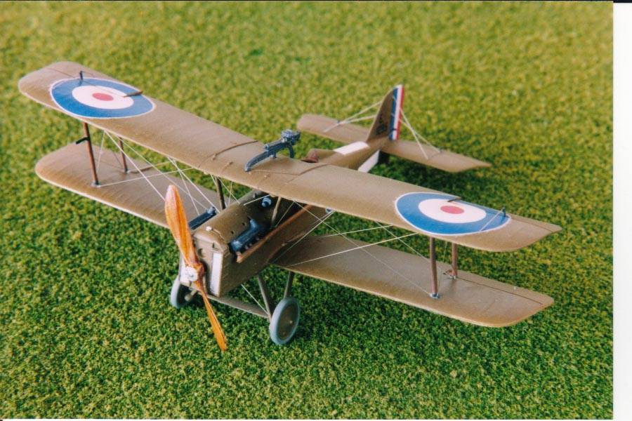
Painting was next and I used an old mixture of enamel paints for the CDL with which I painted the underside of the flying surfaces. The enamel paint plus a brushed coat of Future allowed worry-free masking so that I could then paint the remainder in PC-10, for which I used Dark Earth acrylic. At this point, I painted and glued on the exhaust pipes. I should also have glued on the gun sight but foolishly waited until the top wing was on - I do not recommend that. 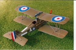 Once this had dried it was time to mount the upper wing. I used my tried and trusted method of magnetic strips and Play-Doh. This is extremely straightforward. I took a couple of magnet strips from a roll that I bought in a hardware store. I covered the sticky side of the strips with tape. I laid the lower wing-fuselage subassembly on a metal surface: I used a tin lid. Then I laid a magnet strip chord-wise over each wing so that the subassembly was held in place. Then I made, small cube-shaped lumps of Play-Doh about the height of the interplane gap and stuck them onto the lower wing's upper surface. I glued the interplane struts to the upper wing using Testors orange tube glue. When that had set up a bit, carefully laid the top wing onto the Play-Doh and gently pushed down until the struts were aligned with the lower wing's strut holes. Once the wing and struts were in place, I used the Touch 'n' Flow filled with Pro Weld glue to adhere the struts. Take care when you press down to get the struts into place. I pressed too hard and was not watching carefully, and I accidentally broke two interplane struts. I glued them using Pro Weld but had to restart the top wing mounting process. I was sure the kit's cabane struts would not fit but a couple of them did. Nevertheless, I had to make a coupe from plastic rod, which I sanded down to an oval shape. Once this had dried it was time to mount the upper wing. I used my tried and trusted method of magnetic strips and Play-Doh. This is extremely straightforward. I took a couple of magnet strips from a roll that I bought in a hardware store. I covered the sticky side of the strips with tape. I laid the lower wing-fuselage subassembly on a metal surface: I used a tin lid. Then I laid a magnet strip chord-wise over each wing so that the subassembly was held in place. Then I made, small cube-shaped lumps of Play-Doh about the height of the interplane gap and stuck them onto the lower wing's upper surface. I glued the interplane struts to the upper wing using Testors orange tube glue. When that had set up a bit, carefully laid the top wing onto the Play-Doh and gently pushed down until the struts were aligned with the lower wing's strut holes. Once the wing and struts were in place, I used the Touch 'n' Flow filled with Pro Weld glue to adhere the struts. Take care when you press down to get the struts into place. I pressed too hard and was not watching carefully, and I accidentally broke two interplane struts. I glued them using Pro Weld but had to restart the top wing mounting process. I was sure the kit's cabane struts would not fit but a couple of them did. Nevertheless, I had to make a coupe from plastic rod, which I sanded down to an oval shape.
Landing gear and decals I painted the landing gear struts with Dark Earth and the tyres a pale grey. The landing gear fit well. Prior to mounting the top wing, I had drilled small holes on the underside to accept the landing gear struts. Once the landing gear was in place, I glued it with Pro Weld.  The kit's decals are fine. I decided to use the scheme for Mick Mannock's aeroplane for No. 74 Squadron. I coated all the surfaces with Future but still found that some of the decals silvered: that was my own fault. I was forced to spend some time poking the silvered part of decals with a sharp pin and applying Solvaset. That, plus some judicious use of pastel chalks removed the silvering effect. I tried the decals that were supposed to represent the little triangular windows in the corners of the flying surfaces. On the real thing, the pulleys and lines that actuate the control surfaces can be seen through these windows. Unfortunately, I felt these decals were not realistic so I simply left them off. At this point, scratch building little windows did not appeal to me, so I left the model as it was. The kit's decals are fine. I decided to use the scheme for Mick Mannock's aeroplane for No. 74 Squadron. I coated all the surfaces with Future but still found that some of the decals silvered: that was my own fault. I was forced to spend some time poking the silvered part of decals with a sharp pin and applying Solvaset. That, plus some judicious use of pastel chalks removed the silvering effect. I tried the decals that were supposed to represent the little triangular windows in the corners of the flying surfaces. On the real thing, the pulleys and lines that actuate the control surfaces can be seen through these windows. Unfortunately, I felt these decals were not realistic so I simply left them off. At this point, scratch building little windows did not appeal to me, so I left the model as it was.
Rigging was next and for this I used my usual 0.005-inch straight wire from Small Parts Inc. - may that company live forever! Rigging the SE5a is more difficult than for most single-bay biplanes with a lot of extra lines. I made the aileron control horns from plastic card. I then glued on the Lewis gun onto he top wing. The prongs on the gun mount do not match the position of the holes in the top wing, so the instructions have you cut off the prongs: I had wondered about this initially. Once the Lewis gun is on though, it looks fine. After a coat of Testors Clear Flat, I added the propeller and the windscreen from the kit's acetate sheet. However, I did not use the acetate sheet for the little window on the fuselage. For that, I used Model Master Clear parts Cement & Window Maker. I put some on the brush and then dipped the brush into the window hole until a film covered the opening. The film dries clear. Conclusion 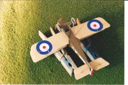 This is a good kit and excellent value for money. One needs to take care when fitting the fuselage pieces due to the multiple pieces but this is a huge improvement on the old Esci and Revell kits. Without too much perseverance, the kit builds into a nice replica of the SE5a and with a little extra effort, one could add more detail than the kit provides, to make a really outstanding model. This is a good kit and excellent value for money. One needs to take care when fitting the fuselage pieces due to the multiple pieces but this is a huge improvement on the old Esci and Revell kits. Without too much perseverance, the kit builds into a nice replica of the SE5a and with a little extra effort, one could add more detail than the kit provides, to make a really outstanding model.
References J. M. Bruce. "RAF SE5a: A Windsock Datafile Special." Albatros Productions Ltd., Berkhamsted, Hertfordshire, United Kingdom. | 


|