Building the Eduard 1/48th Morane-Saulnier Type N
|
 |
  I
think a sure indication that one is building too slow is when a model
company releases a whole new tooling of a kit before you’ve even
built the original tooling of said kit that’s been sitting in your
kit stash since you bought it new ten years ago. Such is the case with
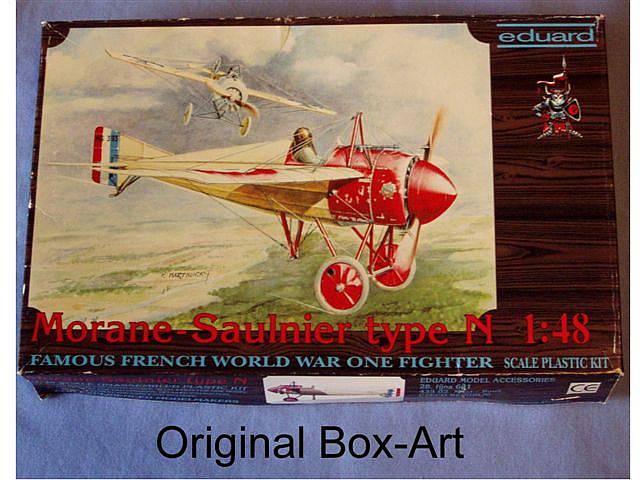
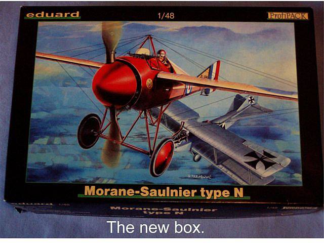
the Eduard Morane~Saulnier N-type, originally released by Eduard in 1995
and released again as a completely new, up to current standards kit in
2004. I
think a sure indication that one is building too slow is when a model
company releases a whole new tooling of a kit before you’ve even
built the original tooling of said kit that’s been sitting in your
kit stash since you bought it new ten years ago. Such is the case with
the Eduard Morane~Saulnier N-type, originally released by Eduard in 1995
and released again as a completely new, up to current standards kit in
2004.
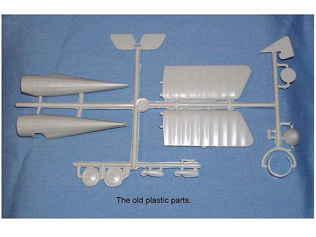
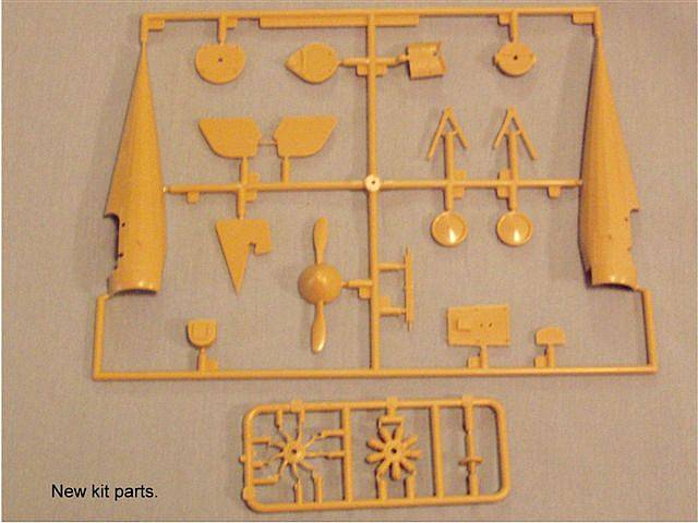
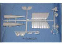
  The
upside, if one would be so kind, is that I am now able to make a direct
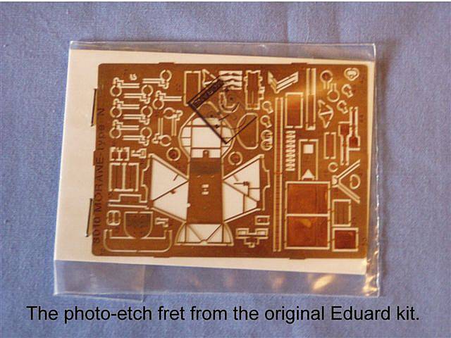
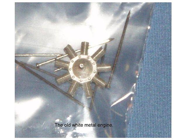
comparison of the two kits here and now. In a nutshell, the old kit has
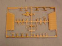
a few basic but useable plastic parts and a lot of photo etch details.
The new kit features lots more plastic parts of much higher quality with
less emphasis on photo etch detail. The
upside, if one would be so kind, is that I am now able to make a direct
comparison of the two kits here and now. In a nutshell, the old kit has
a few basic but useable plastic parts and a lot of photo etch details.
The new kit features lots more plastic parts of much higher quality with
less emphasis on photo etch detail.
  The
downside is that any motivation I may have had for building the old Eduard
kit has been diminished, at least for the time being. However, if one
were to combine the best of both kits, a stunning model could be produced
with not a lot of effort. The
downside is that any motivation I may have had for building the old Eduard
kit has been diminished, at least for the time being. However, if one
were to combine the best of both kits, a stunning model could be produced
with not a lot of effort.
The Build
  Typical
of most airplane models, assembly starts with the cockpit and engine.
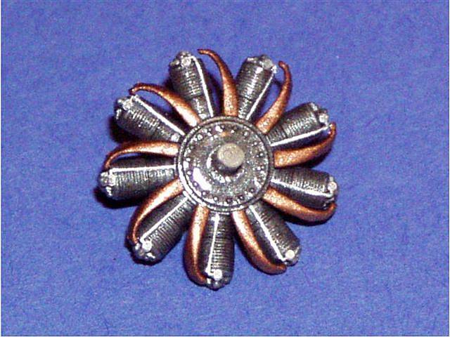
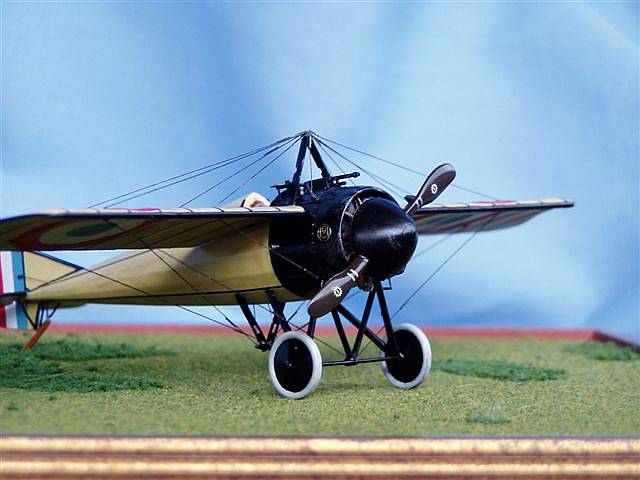
I started with the engine. The detail on this new engine is superb. However,
my example showed signs of mold misalignment. I did lose some cooling
fin detail on the cylinders while scraping the mold seam but the engine
is mostly cowled and hidden behind a large spinner and it would take a
knowledgeable and trained eye to point out the missing detail. The real
problem with the misalignment is that it causes the engine to sit a bit Typical
of most airplane models, assembly starts with the cockpit and engine.
I started with the engine. The detail on this new engine is superb. However,
my example showed signs of mold misalignment. I did lose some cooling
fin detail on the cylinders while scraping the mold seam but the engine
is mostly cowled and hidden behind a large spinner and it would take a
knowledgeable and trained eye to point out the missing detail. The real
problem with the misalignment is that it causes the engine to sit a bit
 cockeyed
in its mounting hole on the firewall. Being a review kit, I wanted to
only use the parts that came in the box but reworking the engine mount
with brass tube would be time well spent, and absolutely necessary if
one should desire an engine that spins with the prop. Since the engine
parts are cast on their own separate sprue, I suspect that these engines
are made in a large production mold that only makes engine parts which
can be used on several different models. So the potential for lots of
misaligned engines is there. cockeyed
in its mounting hole on the firewall. Being a review kit, I wanted to
only use the parts that came in the box but reworking the engine mount
with brass tube would be time well spent, and absolutely necessary if
one should desire an engine that spins with the prop. Since the engine
parts are cast on their own separate sprue, I suspect that these engines
are made in a large production mold that only makes engine parts which
can be used on several different models. So the potential for lots of
misaligned engines is there.
 Aside
from that, the parts went together well and the end result is a convincing
Le Rhone rotary engine. I painted the cylinders and crank case with Humbrol
steel with copper plumbing, and later added a dirty wash to grunge it
up just a bit. Aside
from that, the parts went together well and the end result is a convincing
Le Rhone rotary engine. I painted the cylinders and crank case with Humbrol
steel with copper plumbing, and later added a dirty wash to grunge it
up just a bit.
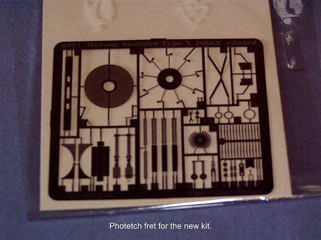
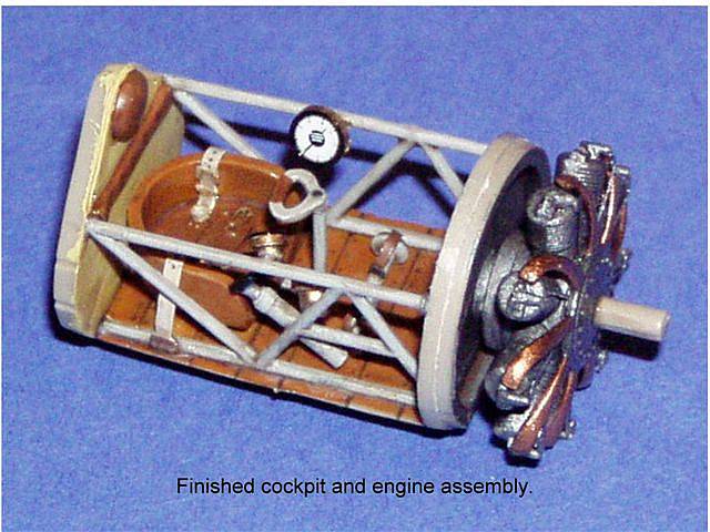
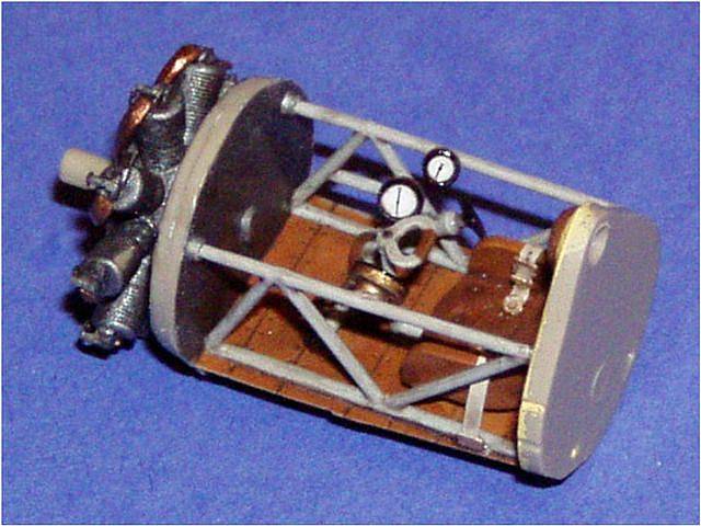
 Next
came the cockpit assembly. This more or less just fell together but the
photo etch detail bits did add an extra hour or so to the job. However,
the end result was worth it as the seat harness is a must and the instrument
bezels improve the gauges considerably. The foot straps on the rudder
bar (parts PE25) are a nice feature but are almost invisible once the
fuselage is closed and the decking in front of the cockpit is installed.
And while I’m on the subject of invisible detail parts, I was tempted
to add some wiring to the backs of the instruments but these too would
have vanished once everything was closed up. Next
came the cockpit assembly. This more or less just fell together but the
photo etch detail bits did add an extra hour or so to the job. However,
the end result was worth it as the seat harness is a must and the instrument
bezels improve the gauges considerably. The foot straps on the rudder
bar (parts PE25) are a nice feature but are almost invisible once the
fuselage is closed and the decking in front of the cockpit is installed.
And while I’m on the subject of invisible detail parts, I was tempted
to add some wiring to the backs of the instruments but these too would
have vanished once everything was closed up.
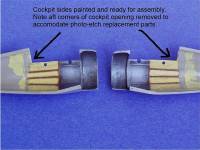  Having
already done the preliminary painting on the fuselage sidewalls, as well
as removing and squaring the aft part of the cockpit opening to accommodate
the photo etch replacement parts, I was ready to proceed with the major
assembly. And here’s where I ran into a speed bump. I wasn’t
able to get the fuselage halves to mate properly around the firewall (part
A17). The fix required some time spent scraping, sanding, fitting, more
scraping, sanding, fitting, until it fit. Not a major hassle but still
a break in my stride. Having
already done the preliminary painting on the fuselage sidewalls, as well
as removing and squaring the aft part of the cockpit opening to accommodate
the photo etch replacement parts, I was ready to proceed with the major
assembly. And here’s where I ran into a speed bump. I wasn’t
able to get the fuselage halves to mate properly around the firewall (part
A17). The fix required some time spent scraping, sanding, fitting, more
scraping, sanding, fitting, until it fit. Not a major hassle but still
a break in my stride.
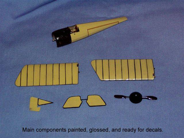
Painting
 With
the fuselage halves closed up, it was time to start painting. Being a
guy who likes to use colors straight from the bottle, I chose my favorite
clear doped linen color, Humbrol 74 Linen for the overall color. After
stuffing the cockpit opening with cotton and masking off the engine, I
applied a few thin coats to the main parts with the airbrush and let them
dry for a day or two. I then masked off the nose section and sprayed the
metal panels flat black, along with the landing gear, wheels, rigging
posts, etc. With
the fuselage halves closed up, it was time to start painting. Being a
guy who likes to use colors straight from the bottle, I chose my favorite
clear doped linen color, Humbrol 74 Linen for the overall color. After
stuffing the cockpit opening with cotton and masking off the engine, I
applied a few thin coats to the main parts with the airbrush and let them
dry for a day or two. I then masked off the nose section and sprayed the
metal panels flat black, along with the landing gear, wheels, rigging
posts, etc.
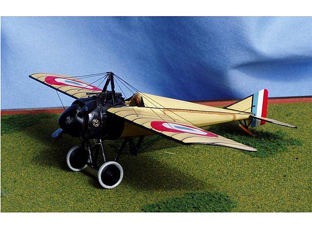
According to the Windsock Datafile on this aircraft, Morane N types
usually had black tapes applied to the edges of the flying surfaces and
along the four main fuselage longerons. These early war Moranes also used
cane battens instead of rib tapes, which were sometimes painted black.
Eduard supplies the tapes for the fuselage and tail planes as decals but
the builder is left to his own  devices
for the wings. For the wing’s edges and battens, I used a black permanent
marker. The edges were done by just running the pen along the edge. The
battens were masked and then ‘inked’ with the marker. devices
for the wings. For the wing’s edges and battens, I used a black permanent
marker. The edges were done by just running the pen along the edge. The
battens were masked and then ‘inked’ with the marker.
After all the black edging and battens were done, a coat of Future was
applied to seal the marker ink and provide a gloss coat for better decal
adhesion.
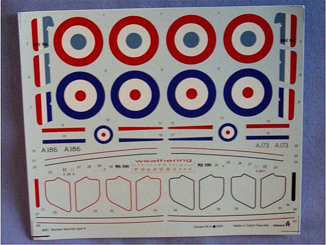
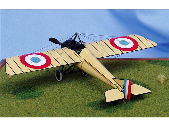
Decals
 Eduard
provides markings for four different aircraft; two in French service and
two in British service. The photo evidence indicates that some Morane
N types didn’t wear any serial numbers at all, the only markings
being national roundels and rudder flash. I decided for my model to represent
a generic, N type. My reason for this is that I thought the model looked
simply elegant with only the national markings. Eduard
provides markings for four different aircraft; two in French service and
two in British service. The photo evidence indicates that some Morane
N types didn’t wear any serial numbers at all, the only markings
being national roundels and rudder flash. I decided for my model to represent
a generic, N type. My reason for this is that I thought the model looked
simply elegant with only the national markings.
The decals went on with no trouble at all and the colors were sufficiently
opaque to let little or none of the black marker show through. What I
really liked was the fact that the decals for the rudder flash were designed
to wrap around the edges just perfectly, requiring no touch-up painting,
or  trimming
of excess decal. I did apply Solv-a-Set to the decals but this was more
out of habit. It really wasn’t necessary at all. trimming
of excess decal. I did apply Solv-a-Set to the decals but this was more
out of habit. It really wasn’t necessary at all.
Once the decals had set overnight, I gave all the linen surfaces a coat
of Future, mixed with Pactra flat clear acrylic and a drop or two of dark
earth acrylic paint to give the details a little depth and tone down the
factory fresh look the model had. Not weathered mind you, just toned down.
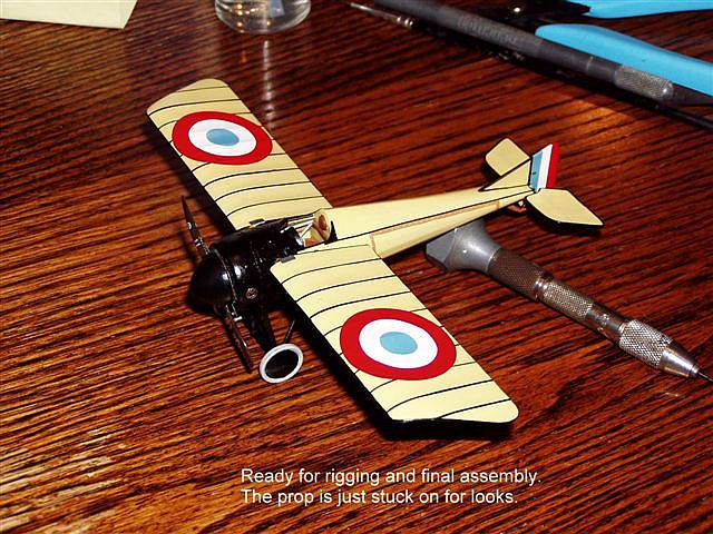
Main Assembly
 With
the decals sealed under the clear coat, the model was ready for the wings
and other bits that make an airplane look like an airplane. While I don’t
want to turn anyone off from building this kit, I feel compelled to point
out a few things that could be done to improve this model. The photographic
evidence sometimes shows a gap between the fuselage and the wing root
big enough for light to pass through. On a 1/48 scale model, this might
be a challenge from an engineering standpoint. I’m just guessing
on that. But Eduard did a good job molding large locator pins on the wing
root that fit snugly into holes on the fuselage which allows the builder
to leave the gap but still have the wing secured well enough so that the
model can be lifted by one wing without falling apart. With
the decals sealed under the clear coat, the model was ready for the wings
and other bits that make an airplane look like an airplane. While I don’t
want to turn anyone off from building this kit, I feel compelled to point
out a few things that could be done to improve this model. The photographic
evidence sometimes shows a gap between the fuselage and the wing root
big enough for light to pass through. On a 1/48 scale model, this might
be a challenge from an engineering standpoint. I’m just guessing
on that. But Eduard did a good job molding large locator pins on the wing
root that fit snugly into holes on the fuselage which allows the builder
to leave the gap but still have the wing secured well enough so that the
model can be lifted by one wing without falling apart.
 However,
the pins on the wing root seem arbitrarily located with little thought
about how the real aircraft was built. The result is the rear pins, if
extended through the fuselage, would go through the pilot. This also leaves
an inaccurate and unsightly pin in a hole on the cockpit sidewalls which
would be a challenge to fill and sand unless one were to attach the wings
before closing the fuselage, which isn’t impossible but not easily
practicable either. The good news is that one has to go looking for it
to see it. Also, leaving the gap between the wing root and fuselage leaves
a small section of the locator pins visible in the gap and requiring attention.
I painted my pins a wood color because I thought it would look better
than trying to hide it under black paint. However,
the pins on the wing root seem arbitrarily located with little thought
about how the real aircraft was built. The result is the rear pins, if
extended through the fuselage, would go through the pilot. This also leaves
an inaccurate and unsightly pin in a hole on the cockpit sidewalls which
would be a challenge to fill and sand unless one were to attach the wings
before closing the fuselage, which isn’t impossible but not easily
practicable either. The good news is that one has to go looking for it
to see it. Also, leaving the gap between the wing root and fuselage leaves
a small section of the locator pins visible in the gap and requiring attention.
I painted my pins a wood color because I thought it would look better
than trying to hide it under black paint.
 The
folks at Eduard would have done better to place the locator pins in line
with the rigging attach points, which in real life are located on the
spars. This would have required a thinner aft pin but it could also have
been longer and set into a deeper socket on the fuselage. Because on the
real aircraft the rear spar passes behind the cockpit. And then Eduard
could have provided photo etch parts to represent the reinforcing around
the hole in the cockpit fabric that the rear spar passes through. To make
this correction on the model should be fairly simple using brass rod and
tube. The only reason I didn’t do it is because I wanted this review
to show what the model looks like straight out the box. And in my opinion,
it’s a damned good looking model. The
folks at Eduard would have done better to place the locator pins in line
with the rigging attach points, which in real life are located on the
spars. This would have required a thinner aft pin but it could also have
been longer and set into a deeper socket on the fuselage. Because on the
real aircraft the rear spar passes behind the cockpit. And then Eduard
could have provided photo etch parts to represent the reinforcing around
the hole in the cockpit fabric that the rear spar passes through. To make
this correction on the model should be fairly simple using brass rod and
tube. The only reason I didn’t do it is because I wanted this review
to show what the model looks like straight out the box. And in my opinion,
it’s a damned good looking model.
 While
I’m picking nits, I might as well address the padded headrest in
the cockpit. This is molded onto the panel behind the seat. However, because
of the thickness of the plastic on the fuselage halves, the headrest sits
too low. The top of the rest should sit just about flush with the top
center fuselage stringer. Any builders with AMS could remove the molded
on cushioned headrest, and reattach it in the proper position later, which
would make filling the ugly seam where the rear panel meets the fuselage
halves easier to accomplish. And I think that about does it for any complaints
I might have about this model. While
I’m picking nits, I might as well address the padded headrest in
the cockpit. This is molded onto the panel behind the seat. However, because
of the thickness of the plastic on the fuselage halves, the headrest sits
too low. The top of the rest should sit just about flush with the top
center fuselage stringer. Any builders with AMS could remove the molded
on cushioned headrest, and reattach it in the proper position later, which
would make filling the ugly seam where the rear panel meets the fuselage
halves easier to accomplish. And I think that about does it for any complaints
I might have about this model.
 One
other modification that would be wise to make is the result of Eduard
doing it right. The connecting rod/spar on the full flying horizontal
stabilizer is molded to scale thickness. It looks lovely but is very delicate.
I was advised by another builder to attach this part last. And when he
said last he meant last. I put mine on after the wings and landing gear
were installed and then proceeded to break it two or three times during
the rigging phase. I strongly recommend replacing the connecting bar with
a piece of steel rod epoxied into the elevators. One
other modification that would be wise to make is the result of Eduard
doing it right. The connecting rod/spar on the full flying horizontal
stabilizer is molded to scale thickness. It looks lovely but is very delicate.
I was advised by another builder to attach this part last. And when he
said last he meant last. I put mine on after the wings and landing gear
were installed and then proceeded to break it two or three times during
the rigging phase. I strongly recommend replacing the connecting bar with
a piece of steel rod epoxied into the elevators.
All in all, the main assembly was a snap. Everything fit well and fell
into place as it was meant to. I couldn’t have asked for anything
better.
Final Assembly and Rigging
The last bits were the installation of the machine gun, rigging and
prop. Eduard gives a choice of  Lewis
gun for the British version and a Hotchkiss for the French version. My
French service machine used the Hotchkiss and at this point I found myself
wishing I had chosen to build a machine in British service. There were
no problems with the Hotchkiss except for my own fingers which seemed
to have lost all dexterity just when I needed it most. However, looking
at all the photo etch on the Lewis gun, I’m sure my spastic fingers
would have had just as much trouble with that gun. Lewis
gun for the British version and a Hotchkiss for the French version. My
French service machine used the Hotchkiss and at this point I found myself
wishing I had chosen to build a machine in British service. There were
no problems with the Hotchkiss except for my own fingers which seemed
to have lost all dexterity just when I needed it most. However, looking
at all the photo etch on the Lewis gun, I’m sure my spastic fingers
would have had just as much trouble with that gun.
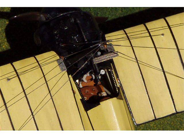
I also lost the rigging pulley bracket (part PE18) and had to scratch
build a replacement which just doesn’t look as good as the photo
etch part would have. Fortunately one can hardly see it mixed in with
all those other black parts. The photo etched parts for the cockpit trim
(PE 10, 11 and 15) really enhance the cockpit opening and whomever thought
to supply these parts deserves a big pat on the back.
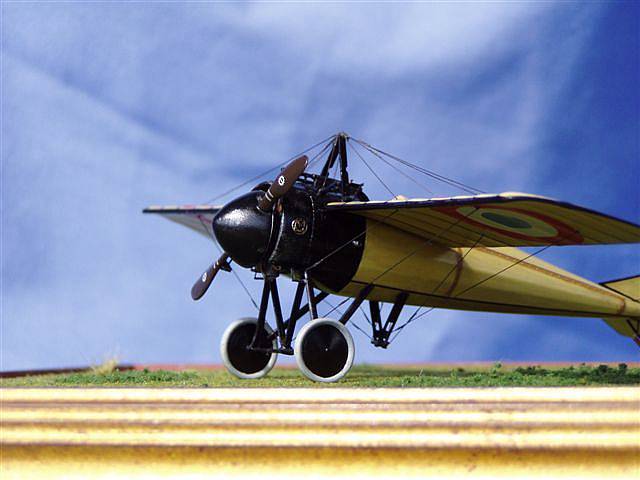
I rigged the model using .008 brass wire, darkened in Blacken-It, a
selenous acid and copper chloride/copper carbonate solution used by model
railroaders to blacken brass rails. Being a  monoplane,
the rigging was pretty simple, even if it is a lot of wires. One less
than perfect part is the control horn on the wing warping system (part
B19). It just doesn’t fit into the photo etch rigging post the way
it was meant to. I had to cut off the ends of the axel post to get it
to fit into its slot. Eduard also provides photo etched turn buckles,
but only enough for one end of each wire whereas the photos of the real
aircraft show them on each end. However, I’ve shown the model to
a few modeling friends so far and not one of them have even seemed to
notice the buckles that are there. Que sara. monoplane,
the rigging was pretty simple, even if it is a lot of wires. One less
than perfect part is the control horn on the wing warping system (part
B19). It just doesn’t fit into the photo etch rigging post the way
it was meant to. I had to cut off the ends of the axel post to get it
to fit into its slot. Eduard also provides photo etched turn buckles,
but only enough for one end of each wire whereas the photos of the real
aircraft show them on each end. However, I’ve shown the model to
a few modeling friends so far and not one of them have even seemed to
notice the buckles that are there. Que sara.
The final part was the propeller. No comments here other than to say
one might add something to represent the bolt that holds the bullet deflectors
(parts B9 and B10) to the radius bar (part PE2). It shows up in the photos
of the real aircraft.
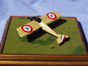
Conclusion
 This
is a really sweet little kit. The overall accuracy looks pretty good compared
to the drawings in the Datafile, with just an occasional discrepancy of
a millimeter or so. Were it not for the extra time required for all the
photo etch and masking off the rib battens, a very nice looking model
could easily be put together in a week of evenings. While fixing the wing
locator pins and headrest would improve the model, this shouldn’t
dissuade those less ambitious from having a go at it. I highly recommend
this kit for anyone. It would also make a good subject for a first attempt
at rigging. This
is a really sweet little kit. The overall accuracy looks pretty good compared
to the drawings in the Datafile, with just an occasional discrepancy of
a millimeter or so. Were it not for the extra time required for all the
photo etch and masking off the rib battens, a very nice looking model
could easily be put together in a week of evenings. While fixing the wing
locator pins and headrest would improve the model, this shouldn’t
dissuade those less ambitious from having a go at it. I highly recommend
this kit for anyone. It would also make a good subject for a first attempt
at rigging.
I’d like to thank the guys at Internet Modeler and Eduard
for the review sample.
References
Windsock Datafile 58, Morane~Saulnier Types N,I,V by J.M. Bruce
|
|