
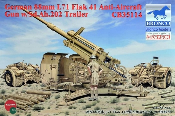
Bronco 1/35 German 88mm L71 FlaK 41 - Part 2
By Don Barry
Kit# CB-35114
MSRP $70.00
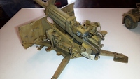
 Good morning, boys and girls. I’m almost sad to say the model is finished. As the instructions mentioned, this is a “precision molded plastic kit with exceptionally fine detail...” They tell the truth. For example, the “B” sprue has part numbers up to 114, with no duplications, many of which are quite small. It is a challenging kit because of the subject’s inherent complexity, not through any shortcomings of the kit itself. I encountered no fit issues, no flash, and only a very few ejector marks that needed filling. Most are on larger pieces, where they are subsequently covered. Mold seams are not prominent and are easily cleaned up.
 In many cases, builders will find it prudent to do most seam finishing while the part is still on the sprue, particularly in the case of conduits and long linkage bars that are realistically thin. Precision part nippers/cutters are a must to minimize cleanup and avoid damage. Despite an alignment problem caused by me and found too late to fix, I am very happy with the finished product, and proud to have it in my collection.
 I generally followed the directions step for step, with minimal skipping ahead. You will notice parts drawn in red; these are generally parts shown in their final position, as opposed to off to the side, with an arrow. Looking closely, you will see lines in grey; these are areas hidden from direct sight due to the viewing angle and many times show the attachment point. Subassemblies are labeled with a large red numeral in a box; that number is then called for in subsequent steps.
ASSEMBLY
 Steps 1 thru 6 are concerned with the cruciform mount and folding outrigger legs. These are hinged to be workable and will remain so even after painting. You are building sealed box sections here, be aware of excess cement which may not have an outlet to evaporate. And neatness counts; there is plentiful surface detail you won’t want to mar. If you don’t intend to use the ground spikes for emplacement, go ahead and glue them in their storage areas.
 Steps 7 and 8 cover the construction of the carriage inner panels. Make sure the elevation gear will rotate fully, even though it clicks going round. This will hold the elevation setting later.
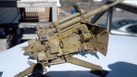
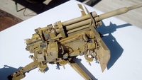
Steps 9 thru 16 cover the barrel and breech assembly, and this is where my mistake occurred. Tape F-1 and F-23 together. After gluing breech assembly to barrel in step 10, glue F-10 to barrel. Test fit to F-1/23 and adjust breech by twisting if necessary to make sure it is square to F-10 and that is square to F-1/23. Mine wound up a bit twisted to the left, just enough to be noticeable.
 Work carefully when constructing the breech, the diagrams often show the breech rotated from one step to the next. In step 14, be aware: B-48 and 49 attach INSIDE the bolt lines on F-22. I found photo-etched parts P-47 difficult to curve due to their small size. I finally annealed them and they were much easier to form. I decided to leave F-29, the muzzle section, loose until later, to ease handling.
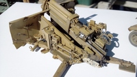
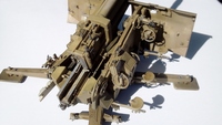
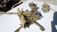 Steps 17 thru 30 fully assemble the side panels of the carriage and trap the barrel assembly between them. Loads of tiny parts are assembled here, but nothing terribly difficult. I draw a line thru the part number when it is used; this helps to keep things straight. I advise reading ahead and deciding if your style of building dictates a change in sequence. Once I had step 18 completed, I glued it to the floor, F-21/40, from step 8. It fully cured in the time it took to complete steps 19, 20 and 21, which were then attached as directed. This was set aside while the other panel’s subassemblies were built and attached. Once step 30 was completed, I had 4 major components: cruciform base, barrel assembly, left panel and floor, and the right panel.
 These were then painted, had a first wash applied, and a light coat of Future applied. (See painting sequence later in this review.) I applied cement sparingly to the floor/right panel joint, trapped the barrel, and then finished cementing. Parts B-71 and 72 were able to be added after the barrel was trapped, before the cemented joints had set up. It would have been handy to have another pair of tentacles to manipulate everything, but the fit was good enough to not be an issue. Everything went together as advertised, with minimal struggle or bad language.
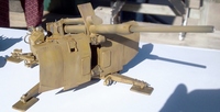
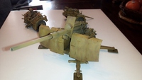
Steps 31 through 36 cover the building of the shields and mounting of the gun to the cruciform platform. The builder must decide whether to assemble in transport or combat configuration, as was also the case in prior steps. You may notice that the locator pegs/holes are mirror images of each other, just extra insurance that all goes as planned. The gun assembly is not positively locked to the turntable, part F-39, so it rocks and does not sit level. Any sort of locking washer was not provided, so I picked an angle I liked, and glued the gun to the base.
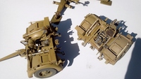
 Steps 39 thru 52 cover the building of the bogie units, supplied by Dragon. I encountered no fit issues with these complex assemblies. Everything fit together well, with no surprises. The tires aren’t supplied by Dragon, they are Bronco items, and do have a “weighted” bulge/flat spot to simulate the weight of the gun. I marked them with a permanent Sharpie to ensure they ended up in the right place. I added retaining chains to the hitch pins from the spares box. Other than that, and an odd Grandt line nut where appropriate, this kit is straight from the box. I skipped steps 51 and 52, attaching bogie units to the base, as I had built the gun in firing position.
PAINTING
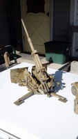 I chose to finish the model in overall German Dark Yellow, using a bottle of Floquil #303124, from their old Military Colors series, used straight from the bottle, thinned as needed. I then darkened that paint with 10% Steam Power Black and 10% Railroad Tie Brown, and thinned it to the consistency of a strong wash. This was used to post shade shadow areas, recesses, the elevation gear and trunnions, etc. After letting this dry for 2 full days, a thin overall wash was applied using
I thoroughly enjoyed building this model. I am happy it is finished, as I was eager to see it in its entirety, but if I had another, I’d gladly start tomorrow. The complexity and detail should not be intimidating. Just take it one step at a time. The construction is logically laid out, and the instructions are easy to follow. There is not a lot of jumping around between several sprues at a time, which makes work easier. The only frustrating moments were when I dropped parts, which were invariably small and seemed to bounce an inordinately long distance from their point of impact. In all aspects, I rate this kit very well recommended, two thumbs way up.
Thank you to Stevens International for supplying this review kit, and to my generous editor for allowing me to build it. Happy modeling!