About the Real Atomic Cannon
Before going further, I'll recap some material I wrote for the in-box review about the real atomic cannon. About twenty were made in two arsenals located in New York and Massachusetts although the first was designed and made at the Picatinney Arsenal in New Jersey. It was the Picatinney one that fired the United States' one-and-only atomic artillery shell which had a yield of fifteen kilotons. Some said that was equal to the Hiroshima bomb. Considering it could fire atomic shells, it was a good thing the atomic cannon, also called the M-65, had a range of twenty miles which kept at least it and its crew safe from the blast. It could also fire 280mm shells that weighed 600 pounds each and were called the T-124. If you're wondering how this compared to a navy gun, it would be an 11-inch gun.
The Army had transporters designed to haul the gun carriage on paved and unpaved roads. A transporter called the M-249 was ahead of the 47-ton gun carriage and its counterpart, the M-250, was another transporter attached to the rear of the gun carriage. Both, designed by the Kenworth Truck Company, had six-cylinder 345-horsepower engines that could move the assembly up to 45 mph on paved roads although they usually traveled at a safer 30 mph.
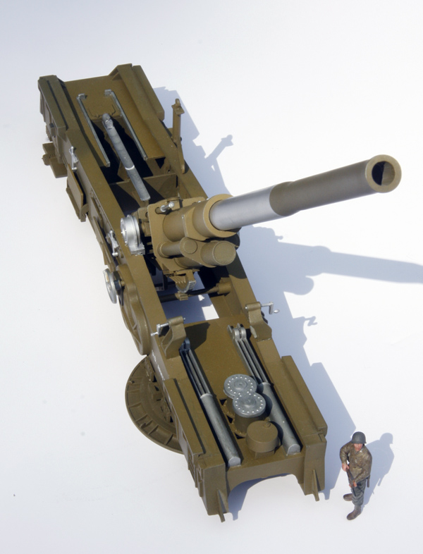
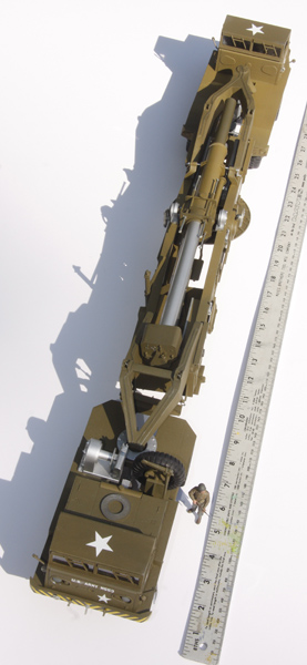
The gun carriage measured 38 feet, 5 inches (11.7m) long and sources reported the gun could be readied for action in 7 minutes. Its reported accuracy was 20 yards at 20 miles. One M-65 was driven through Washington, D.C. during one of President Dwight D. Eisenhower's inaugural parades.
The M-65s were deployed to West Germany and Okinawa. They were deployed in pairs, accompanied by ammunition-carrying vehicles and a crew of 22 soldiers.
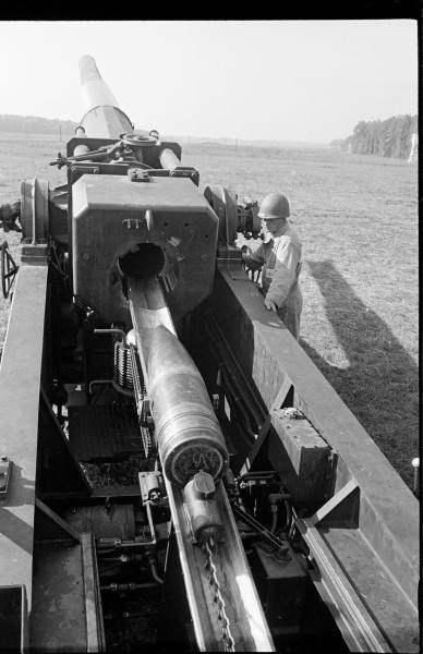
Once set up, the cannon could be maneuvered hydraulically or manually although the rammer operated only hydraulically. It was said to be fired electronically although one person said it could be fired with a lanyard.
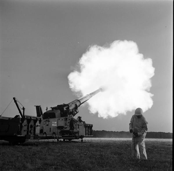
The sole firing of the atomic shell came on May 25, 1953 as one of a series of nuclear weapon tests called Operation UPSHOT-KNOTHOLE. The M-65 fired its shell at a target seven miles away at the Nevada Proving Grounds. Nineteen seconds after firing, the shell exploded 524 feet above the ground as planned. Of the 80 W-9 warheads made, this was the only one fired.
None of the M-65's saw combat and all were retired in 1963. Of those, eight survived the scrappers' torches. They are displayed near Ft. Riley, Kansas; Rock Island Arsenal in Rock Island, Illinois; U.S. Army Ordnance Museum at Aberdeen, Maryland (this one has transporters attached to the gun carriage); Virginia War Museum in Newport News, Virginia; Yuma Proving Ground in Yuma, Arizona; Watervliet Arsenal Museum in Watervliet, New York; National Museum of Nuclear Science and History in Albuquerque, New Mexico; and Ft. Sill Museum, Ft. Sill, Oklahoma which has the cannon that fired the atomic shell (and was nicknamed "Atomic Annie").
If you wonder how the M-65 compared to the German rail guns, the German 283mm guns, transported only on railroads, were 105 feet long, weighed 218 tons and had a range of 40 miles.
Quite often I referred to the Internet for photos of the M-65, usually Googling "Atomic Cannon M-65 Photos" led me to many websites with photos--these helped in many situations. An excellent 10-½-minute video of the atomic shot shows the cannon being transported through Las Vegas to the test site (actually, two M-65s at the site), being set up, loaded and fired. A picture of the atomic shell is at: https://wuxinghongqi.blogspot.com/2009/06/atomic-cannon-in-fablehave-you-seen-it.html.
The Model
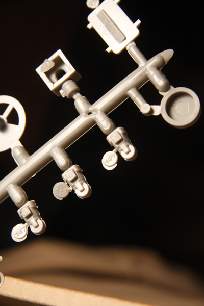
All right, back to the build-up of Renwal's Atomic Cannon. First, remember how I said some pieces were loosely attached to their sprues, the same goes for the tiny round ID tags with the parts' numbers on them. They, too, separate easily from their parts and no parts have ID numbers on the sprues. On top of this, those little round tags have hard-to-read numbers so get used to looking at them very closely under a slanted light.
The sixteen page, thirteen step booklet is pretty straight-forward and easy to follow. If you're expecting FS numbers or paints called out by some manufacturer's name, nope. You're on your own for picking out what colors you will use but honestly, they're pretty basic--olive drab, aluminum, steel and black.
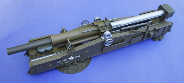
I thought I'd paint this model with rattle-can paints, a decision I came to regret for a reason that has nothing to do with the model. I bought two spray cans of Testors olive drab to paint the appropriate parts of this kit. The paint from the first can went on fine and looked nice. When I used the second can to paint the other paints, its olive drab paint went on nicely too, but it was noticeably darker than the olive drab of the first can.....@%#&@%&@%*!!!!!! I bought a third can...its paint matched that of the first can so I used this one to cover as much of darker shades from of the second can but couldn't get them all. I muttered some nasty words and rationalized that maybe someone in the army did the same years ago which is the explanation I'll use if anyone remarks that my model has different shades of olive drab.
The Gun and Gun Carriage
As is usual when building models, one has to make decisions about what to paint first before gluing or gluing before painting and this kit is just like that. With eight pieces making up the gun barrel and its cradle, one can expect some sanding, inspecting, perhaps some filling (I used Mr. Surface 500) and sanding again. I don't remember any other sanding and filling on the gun carriage and gun.
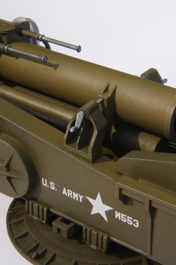
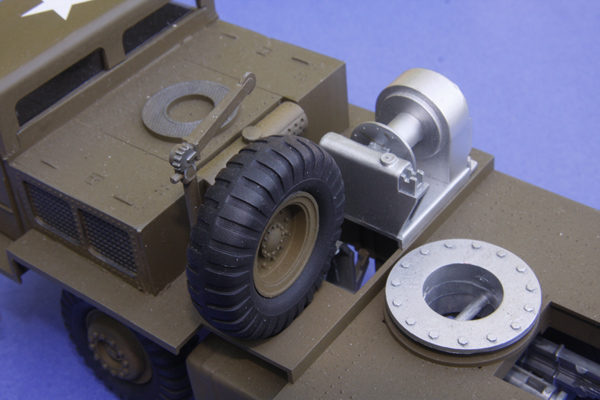
Part #96, the gun carriage's crane for moving artillery shells onto the rammer chute is spartan, just one piece. If you want to detail it with cables and a shell carrier, you'll need to refer to photos that show those items on the real cranes.
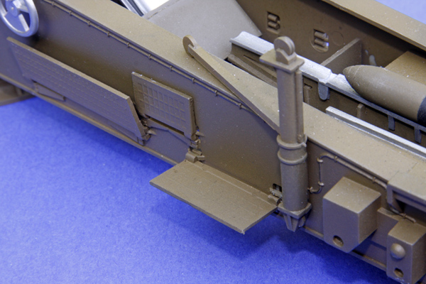
The Lifting Forks
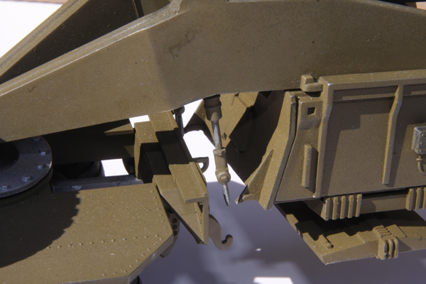
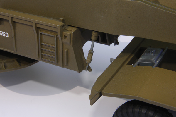
Two hoist cylinders (Parts # 22) fit into each lifting fork to help connect it to the gun carriage. The ones for the rear lifting fork fit fine. Those for the front lifting fork, however, are a tiny bit short, maybe one or two millimeters, of reaching the lifting hooks on the gun carriage; I'll have to figure a way to lengthen them to make that connection.
Sanding and Scraping
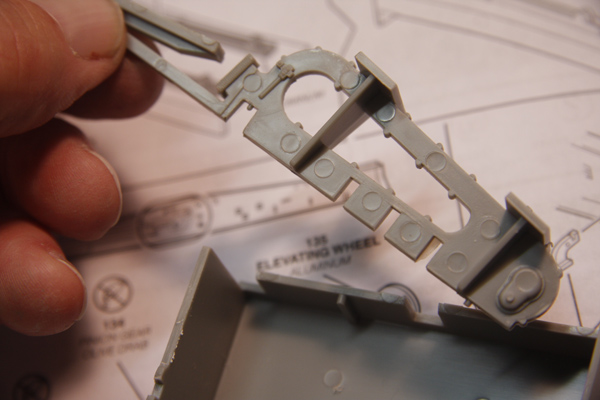
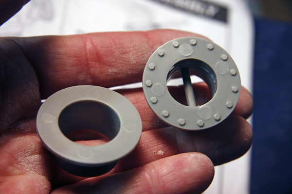 I saw no sink marks on all the pieces but plenty of ejection pin marks but most of those were hidden during the assembly with a few exceptions such as one side of Part 122, the rammer base, which has at least thirteen of those marks. Also, one piece bedeviled me, Part #53, the fork swivel which is part of one lifting fork assembly that connects the gun carriage to a transporter. The round flat head of this piece has fifteen prominently raised bolt heads and between some of those are four ejection pin marks. Those were not easy to sand or file away but thankfully they were the only ones that gave me trouble. You'll find an assortment of seam lines to sand or scrape on various pieces too.
The Transporters
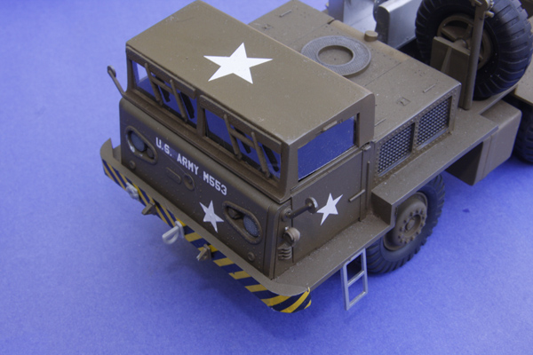
The two .50-caliber machine guns to be mounted on the roofs of the transporters' cabs confused me. In other army vehicles with such arrangements, I've seen openings in the roofs for the gunners to stand up in the vehicles while manning the guns. The roofs for the atomic cannon transporters have no such openings.
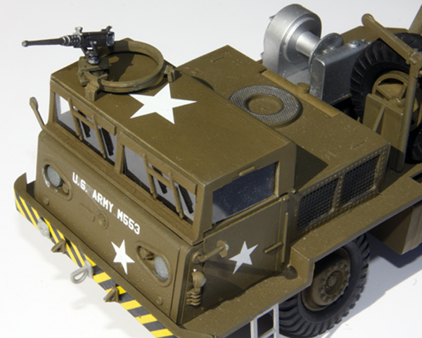
Most photos of the real transporters showed them without the machine gun rings and I think I found only one that showed a transporter with a machine gun on its roof.
Some parts that form the drivers' cabs and engine compartments don't fit snug and need some work before gluing to fit properly. The interiors are sparse and leave plenty of room for adding details.
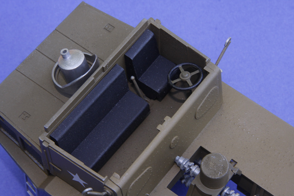
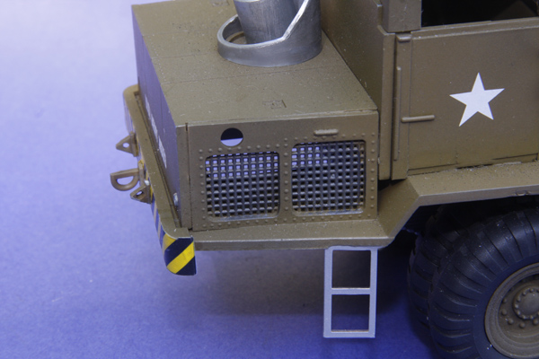 See my photo and you'll see I should have put something across the floor of the engine compartment to avoid seeing the ground through the big hole there....sigh.
Miscellaneous
The decals went on without problems. I did my usual method of dipping a decal into water and letting it sit on my work table for a few moments while brushing a 50-50 white glue/water mix on where the decal is to be applied. Even if you have matte surfaces, this keeps the carrier film of the decals from showing.....and saves a modeler from having to apply glossy coats before applying decals. I owe Randy Fields and Marvin Howell, both of IPMS Ft. Crook in Omaha, NE, a tip of the hat for teaching me that trick.
I assembled the two artillery shells and sanded their seams. Photos show various ways to depict the shells so you have your choice of styles. I didn't assemble the ammunition cart because I just didn't like it...it looks too scrawny to be transporting artillery shells this size but since I haven't hung around armor and artillery much, who am I to know?
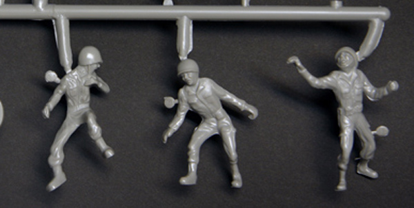
As for the figures representing the crew, they look like they were made out of Play-doh with rounded features. One guy had his mouth open wide like the person depicted in Edvard Munch's painting, "The Scream." I'd prefer to use some 1/35 guys even if they're a tad short by scale.
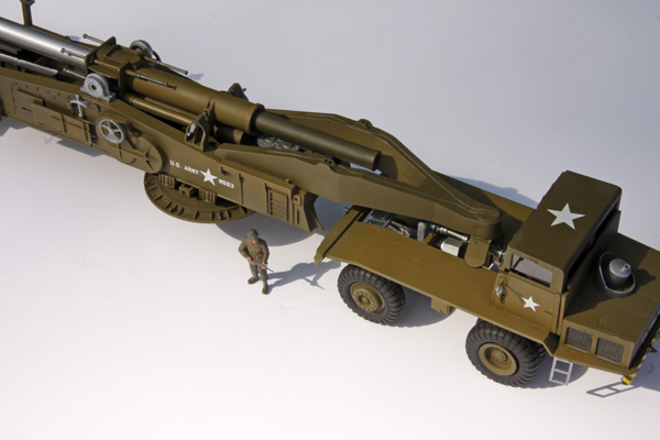
When you attach the transporters to the gun carriage, you'll see why the gun barrel of the model is designed to slide back and forth--not to reproduce the gun's recoil motion but so it doesn't punch through the rear transporter's cab. Nothing in the instructions informs you how the gun barrel is to be set for when the transporters are attached.
And in the End....
I don't know if the kit is still in production but I have seen it around. Revell's re-issue of Renwal's Atomic Cannon (#7811) retails for $56.99.
Thank you to Revell for the review kit.