
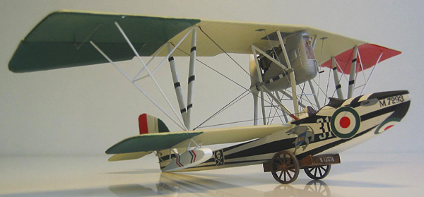
Freightdog/Blue Max 1/48 Macchi M.5
By Paul Thompson
History
Developed in 1917, seeing service through 1918 and beyond, the Macchi M.5 was a successful floatplane fighter built for the Italian naval airservice as a counter to Austro-Hungarian air attacks. The Macchi M series began with the captured Lohner T L40 in 1915. The designs that lead tot the single-seat M.5 began in 1916 and incorporated many elements of Nieuport design . It was used not only by the Regina Marina, but also the US Navy, based at Porto Corsini in 1918. Regarded by many as the best floatplane to see service in the war, 348 were produced. Eventually they were replaced by the M.7 and withdrawn finally by 1924. A full history is to be found in the Windsock Datafile on the type, and a potted one can be found here: https://en.wikipedia.org/wiki/Macchi_M.5
The Kit
I did a First Look for this when I got it. Here's the link: https://www.internetmodeler.com/artman/publish/flaviation/Freightdog-Blue-Max-1-48-Macchi-M-5.php
The Decals
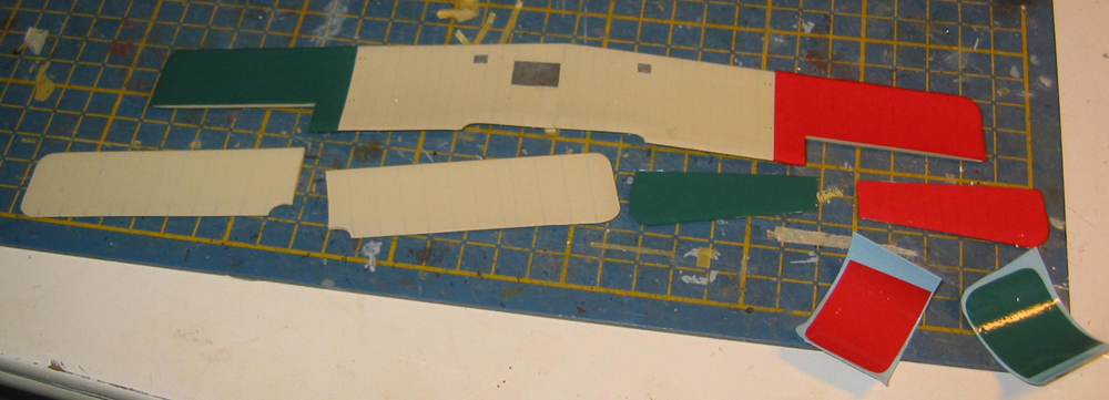
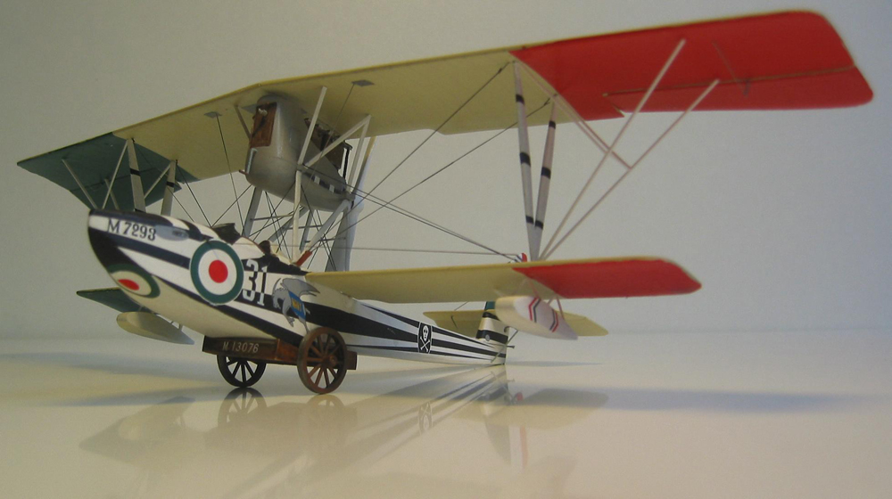
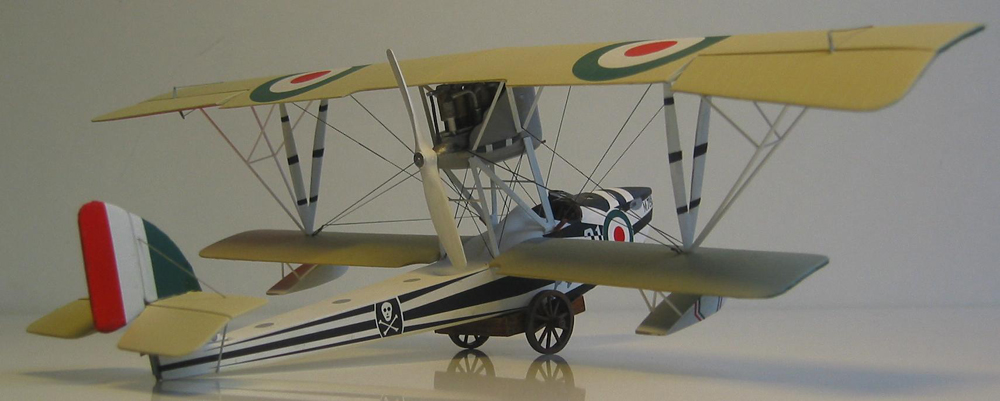
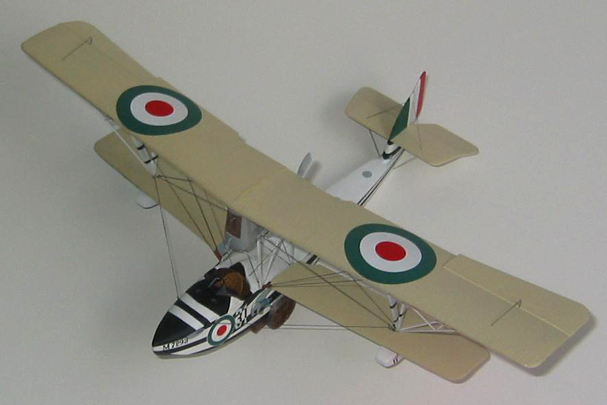
Since then I've received the aftermarket decal set kindly sent by Rowan Broadbent of Pheon Models. This is a brilliant package in his usual style - a booklet with histories of all 12 subjects offered, notes on the Fly and Freightdog kits, high quality 1/48th full colour profiles and plan views, and the decals themselves. The latter come on one large and one smaller sheet, plus two small additions allowing for the handedness of a numeral on one of the options. Decals are beautifully printed. I forgot to photo the package before using it, so here's a link to Pheon's stock page at Britmodeller: https://www.britmodeller.com/forums/index.php?showtopic=60075 Finding and clicking on the appropriate link takes you to a review on Hyperscale. These are all much more colourful examples than those in the kit, eight being from squadriglia of the Regina Marina, with white based dark brown hulls and lots of fancy striping or white triangles. There are also four from the American contingent, and these are altogether more flamboyant. All wings are CDL except the last two American flown ones, which have green uppersurfaces.I chose to do number 10, M7293, flown by Willis B Haviland, commander of the Porto Corsini naval air station from July 1918. He was supposed to be just an administrator, but flew regularly and agressively. He survived the war and died of illness in 1944.
The kit decals are also by Pheon, and the aftermarket package uses the flag markings from these for the wings (or you could paint them if you wanted).
Construction
Wings
Engine
Next, I spent a couple of days quality time with files, knives and sandpaper removing plastic from inside the nacelle, otherwise there's no way the engine can fit. Par for the course with the technology used to make Blue Max kits and can't be helped. Also, as it turned out, a big mistake. This was before I received the Pheon decals, and realised that for most of the decal options you need to cut off the cowling panels.
Fuselage
|
|
|
|
|
|
|
|
|
|
|
|
|
|
|
|
|
|
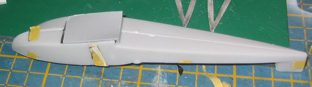
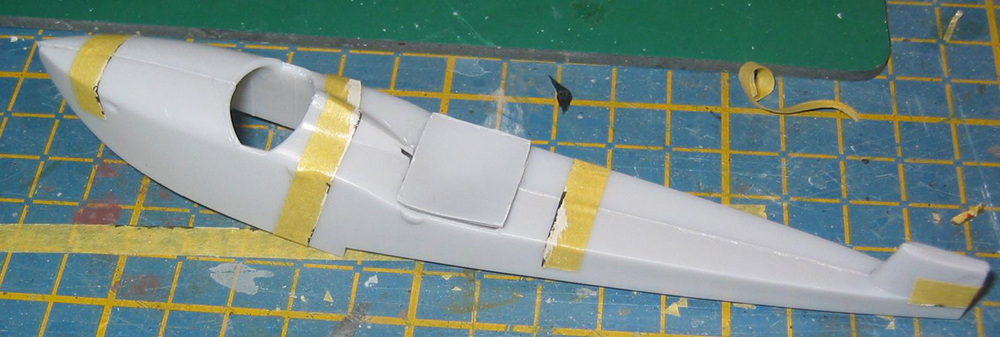
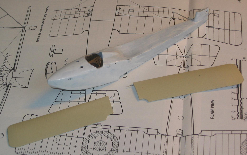
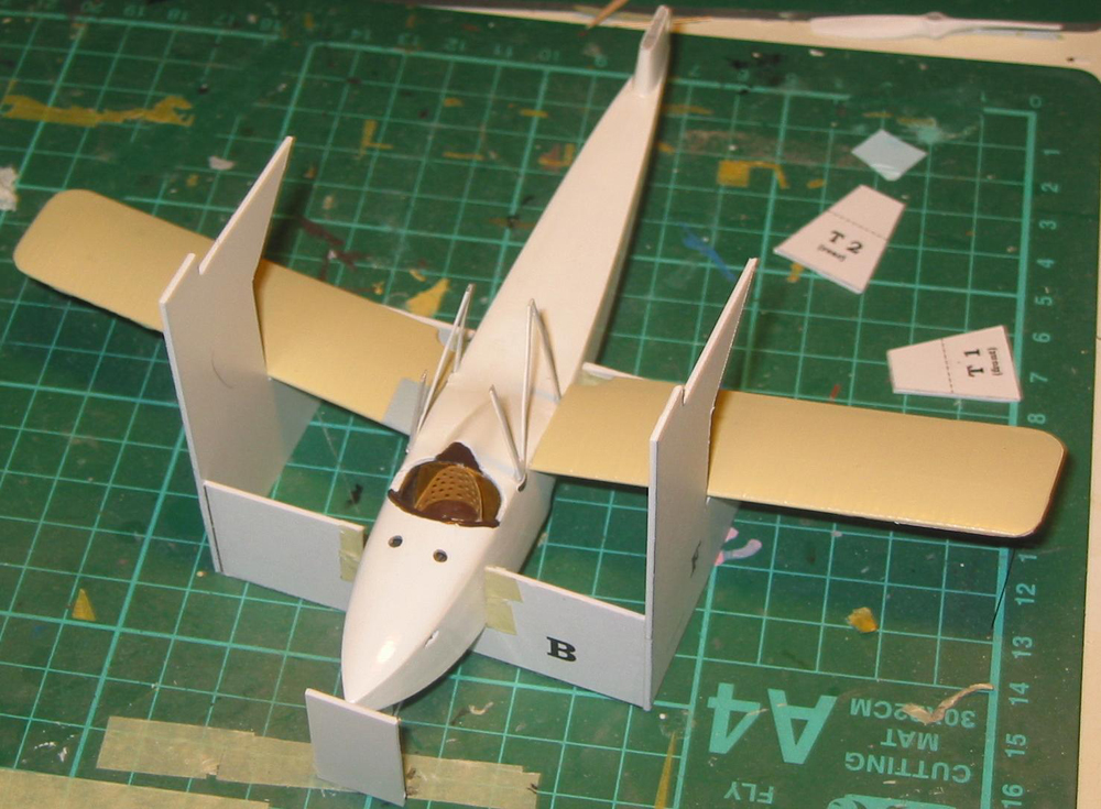
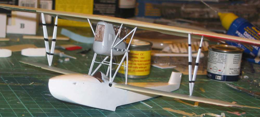
Here be dragons. Tiny, teensey dragons, but potentially adversarial. First, in my example the fuselage halves had warped a fair bit, needing a fair degree of clamping when closing up. Second, one half was 2mm shorter than the other. You can line them up so the cockpit opening and holes for the two inserts match okay, then round the nose and tail a little bit when dried. You should really thin the cockpit sides and replace the simple sidewall detail with plastic strip or sprue afterwards. I didn't, and to be honest it doesn't look too bad. Anyway, thinning the sides would mean modifying the resin parts to fit...........
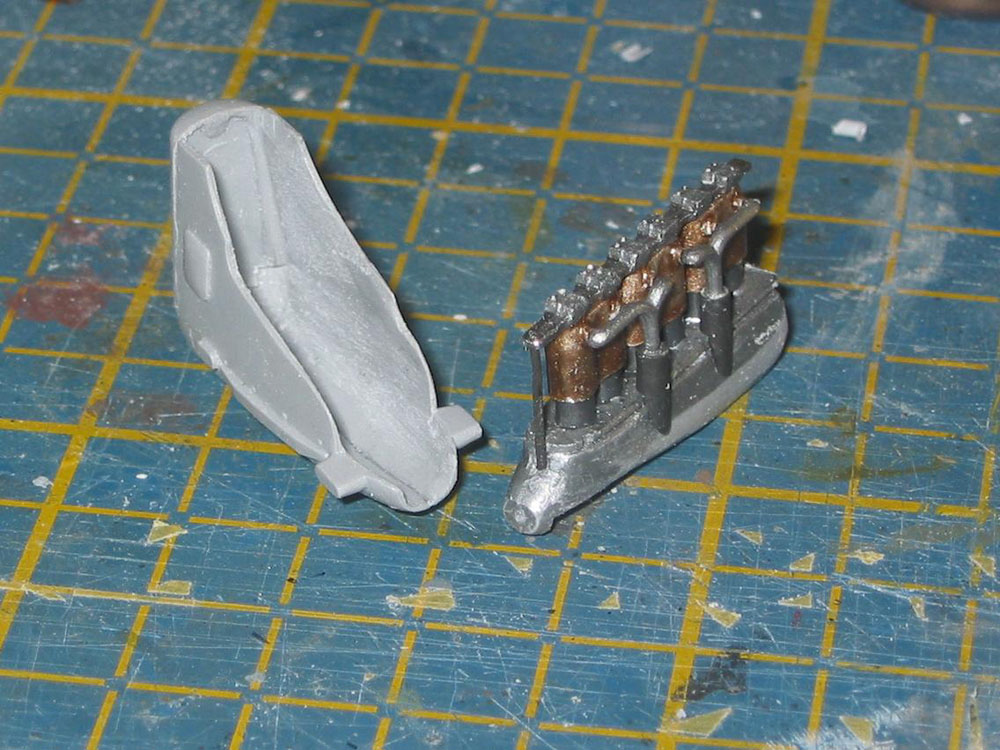
More quality time was spent as instructed fettling the top and bottom inserts until they fit comfortably in the taped up fuselage halves, then the resin rear bulkhead/seat support was CAed in place. The seat bearing part really needs a couple of millimetres taking off the top. As it is, the seat is visibly a little bit too high.
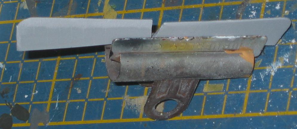
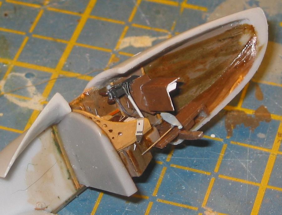
Now comes the part where you have to decide whether or not to use the kit guns. Confusion reigns nicely here. The original configuration was one centrally mounted Fiat-revelli gun, but this was unreliable, so later replaced by two British Vickers guns, according to the records, although Ian Stairs plans say two Fiat guns.. The BM cockpit parts are based on the one cockpit shot in the Windsock Datafile, but although clear, it's, well, not clear. The kit has two white metal Vickers, nicely cast with ammo chutes in place, and you're supposed to stick 'em on sideways. For this to work in real life is impossible, and has no relation to the what you see in the photo. I've seen some wonderful scratchbuilt work where a modeller has taken the installation to really be two Fiats with appropriate wooden ammo tanks, but good as his work is I'm doubtful. The photo just shows the gun butts, and they do look a bit like Fiats, and I've seen a convincing drawing showing how they'd sit with the boxes. However, I think they're really modified Vickers. According to the Harry Woodman book on Vickers m/gs, Italy ordered a lot of Mark 1 Vickers, and they do look a bit like the photo if mounted sideways with modified cocking handles. See what I mean about obsessing? In the end, after wasting much time I just scratched them from scrap plastic stock and made the visible faces of the boxes from plastic card. Guess what? The only bits you'll ever see again without a probe are the ends of the gun butts.
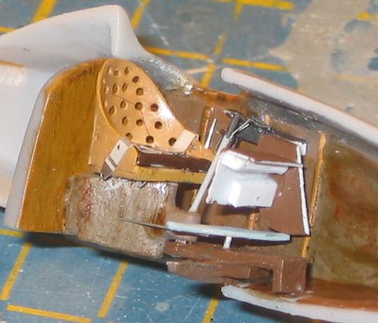
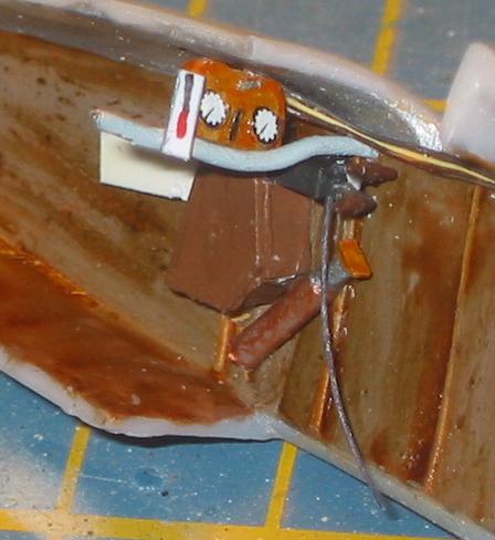
For the rest of the interior I used the kit parts, painted with various acrylics. Be warned and thin the underside of the fore-decking a lot first or you'll never get the little resin instrument panel in the right place. At the same time drill out the two round windows on the upper decking. They're already marked. I added a few little bits of wiring and replaced the resin control column (which has a blob at the end and no triggers) with one scratched according to the Datafile photo. Ther resin seat is lovely, just as well as it's most of what you see when done. I cheated here and added a lap-belt from the glaringly non-existent Eduard Italian set, i.e. I made do with a French one.
After stuffing this lot inside and wiring the triggers to the guns with EZLine, it was time to close the fuselage. Best to do it in stages to get the alignment right, as you would with an older resin kit. I used a combinatipn of Contacta, MEK, and a few blobs of gel CA where things didn't quite meet, aided and abetted by a clamp on the tail and lots of masking tape. After drying out a lot of filler was needed on the top surface, and after adding the hull inserts a lot more.
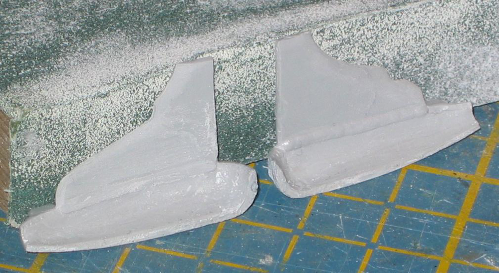
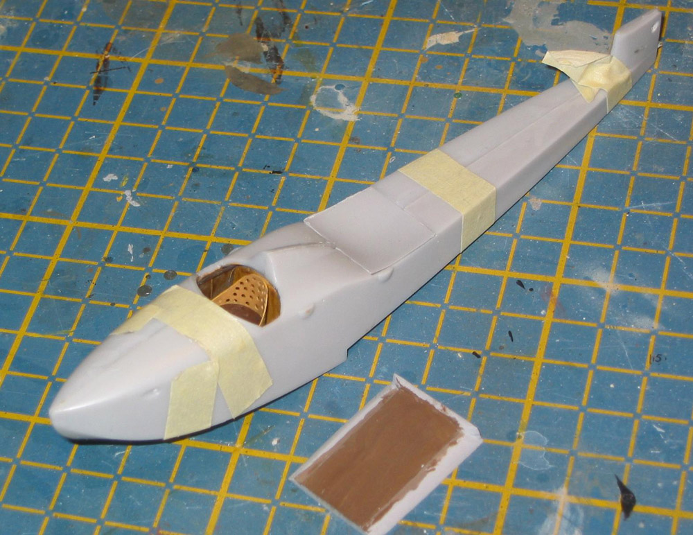
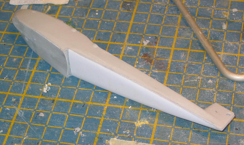
Here's another little dragon that'll try to bite you. Accuracy wise the kit is pretty good compared to the Datafile plan on which I think it was based, except for one feature. I wouldn't have noticed but both Rowan and Dave Hooper (who has done a grown-up build for a paper magazine) point out that Gannon got the rear hull underside slightly wrong. The depth is nearly okay, but the profile is flat, whereas it should be convex. It bows downwards progressively more from the step rearwards to about halfway, then diminishes up to the sternpost. This becomes more visible if you use any of the decals with lots of striping. Having sanded a lot off the bottom anyway to kill the seam I added a sheet of plastic card and with refernce to the handy cross sections in the Datafile, sanded it to shape. In the end I didn't take enough off so the fuselage is a bit too deep. This only would really show up with the decal option I decided to use. B*gger.
Final fuselage stuff was to drill out all the necessary holes, not forgetting that under the tailplane where the elevator cranks come from.
Assembly, Painting, Decalling and Riggin - All One Step Really
|
|
|
|
|
|
|
|
|
|
|
|
|
|
|
|
|
|
|
|
|
|
|
|
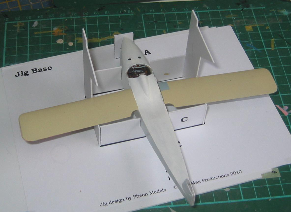
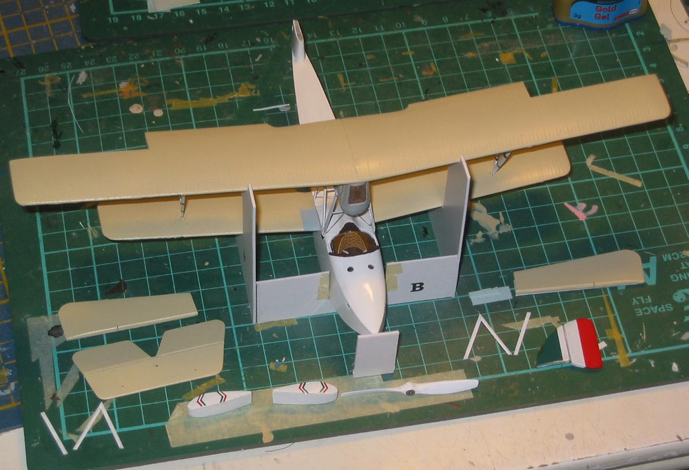
I drilled a hole in the fin, tailplane and where they join the fuselage to aid alignment with a metal pin. After testing this I assembled the Pheon jig. This comes printed on sticky-backed paper to which you add card of your choice and cut out. I used 40thou plastic and it proved very stable. Stuck together with MEK. If you're using one of the highly decalled options you should figure out which might be damaged by the jig walls and leave off if possible until later. I was doing option 10, which is all white with black decal striping, so I left all decals off until the model could be removed from the jig. It helps to sand the jig edges a tiny bit and wrap them with masking tape.
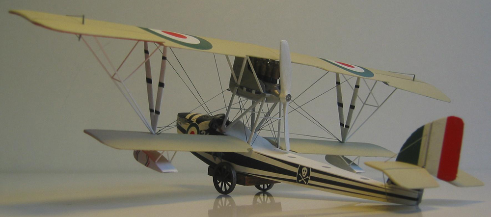
I painted the hull with a lot of white paint then put it in the jig and added the pre-pinned wings. This went perfectly well, giving textbook sweepback and dihedral. The flag decals from the kit sheet had earlier been added to all the wings and sealed in, and here I need to ramble off a bit. The Pheon decals work as near perfectly as any decal can, but because I didn't read the relevant bit in the booklet first I used some Mr Mark setting soloution to help bed them down around the wing edges. Big mistake. two unwanted effects. First, although to begin witht it looks okay, after a couple of hours the decal bleaches. Second, the solution washes the glue off so the damn thing doesn't stick to the edges, which was the whole point anyway. That's why they look ragged at the edges in the completed photos. I spent a lot of time patching the bleached bits with spare bits taken from unused decal items, but found the colours impossible to match when trying to get a neat leading edge using paint. The decals edges had shattered when being trimmed, having been sore abused. Going by how the rest of the decals worked, you should have no problems if using just water, with maybe a smidgen of Micro Sol as recommended in the instructions. End of digression.
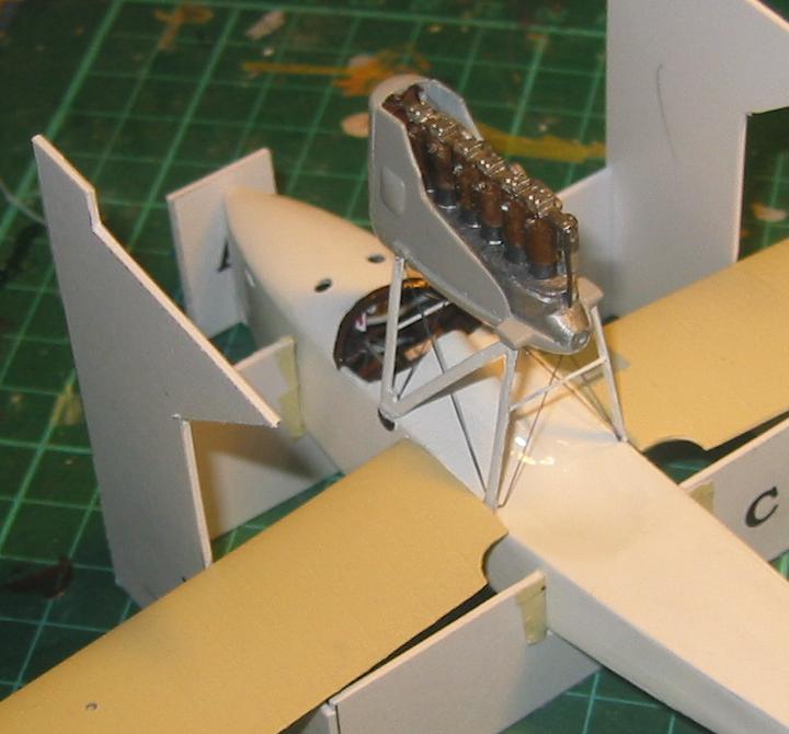
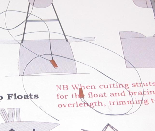
The pewter cradle struts were set up using the separate jig pieces after straightening out a bit using the supplied diagram. They were attached to each other using the supplied wire cut to make three cross pieces. The instructions say to make just two. They missed the middle one, but there is wire enough. You'll need to check the spacing at the top of the cradle to ensure the engine assembly will fit. The whole lot was painted white then plonked in place, and rigged while easily accesible with charcoal EZLine. Then the nacelle (pre-painted Xtracrylic light aircraft grey, with brass radiator and medium grey bands on the strut bearers) was added.
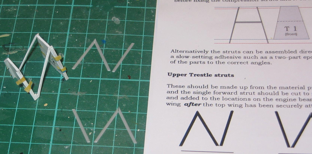
Next up is adding the top wing. The white V struts had been painted and the supplied decal tapes added. These are too short because Rowan had assumed the struts wouldn't be as bulky as they turned out. If they had been thinner, I don't think they'd have been strong enough, so don't be tempted to sand away at them. The decals were extended with black paint. I put the top wing on the jig, and after test fitting put gel CA in all the mounting holes, then sprung the V struts into place, checking for sideways alignment. Left to cure overnight, I found out that if you take the thing out of the jig to fit the top cradle struts, the wing will fall off quite nicely as the turning moment applied to the base of the V struts easily exceeds the shear strength of the CA. Either use epoxy, or lift the whole lot up and add the cradle struts from underneath. These are cut from the supplied stock using the template and trimmed to fit, which is why you need the top wing in place first. Once they're on, the wing is perfectly stable.
At this stage I rigged the model with a mixture of EZLine and rolled copper wire. Butchered chunks of Eduard turnbuckles were used pre-stuck to the EZline to anchor it in the holes. The landing wires appear to be faired with leather or wood. I shaped some strut stock and glued EZLine into a groove cut into the top, then stuck the lot in place. Then I made and installed the overhang bracing. These are very thin struts, and the kit material was really too thick. There's enough rod supplied for the job, but that looks too - round, to my eye, but I found some white plastic stock strip that looks better, and white rod for the bracing that attaches to the middle of it all. They were probably white on my subject anyway, so it avoided another painting step.
The whole model could then be removed from the jig, the empennage added, and all the decals put on.Some of the striping needs to be painted. The guide speculates that the rear hull top was striped also, but I'm not too convinced. The one photo I've seen is inconclusive. I did try, with decal strip, but on reflection removed them. Once dry I inverted it and added the floats. These had already had the struts cut from rod and installed according to the plans, so they were just glued up and dropped carefully in place. While handily upside down I added the tailplane struts from PE 1/32nd RAFwire, and made up the rudder post extension (not supplied, unless it was the one white metal bit I couldn't identify) from shaped strut stock, with added PE control horns. It was deflected the same way I'd deflected the rudder, corresponding with the throw on the rudder pedals. The same Eduard PE set supplied all the required control horns. The two under the elevator were attached to thin grey scrap actuator rods.
Back the right way up the ailerons were CAed in place and control horns and rigging added. The final decals (upper wing roundels) were added and the whole model given a heavy sousing with Xtracolour satin varnish. Once dry I added the windscreen, pre-glazed with Humbrol Clearfix, and glazed the two portholes with the same material. Final additions were the generator? prop and starting handles on the front of the radiator and nacelle, and the propellor (which for once was an easy paint job, being overall white).
Finally, the model needs a handling cart to be displayed effectively. When on land they were always parked on one. I scratched one from card and sprue with invaluable guidance from Dave Hooper. He had some really good ideas there which I won't repeat here because I expect he'll want to do that in his own review.
Conclusions
This was a very enjoyable kit to build, despite the vagueness about the m/g installation and the fix needed to the hull underside, neither of which were really Freightdog's fault. The build was a typical limited run affair, aided hugely by the improved instructions, the quality of the jig, resin and templates, and the general soundness of the basic parts. A skilled modeller could do a vast amount more than I've done - I'm just (I hope) your average guy, but can certainly see the potential in the parts. Both kit and Pheon decals were excellent, despite my self-generated mishap with the flag decals, and I'll be getting another kit if they're still to be had to do one more example. I thoroughly recommend both kit and the Pheon decal set to anyone with an interest in the type. And I've got a pair of really nice Vickers m/gs left over which I can use on a couple of old Sopwith Pup vacs. Yipee!
References
-
Machii M.5 By Gregory Alegi, Windsock Datafile 86.
-
Macchi M.5 (Uncredited, so presumably Ray Rimell) Windsock International Volume 6 Number 6.
With thanks to Dave Hooper and Rowan Broadbent, and also to D.Fernetti, N.Crawford, P.Soares, F.May and S.Weier for their moral support.