Introduction
Roden's 1/32 scale SPAD VII is not a model for beginners. SPADs in and of themselves are difficult models in any scale. The VII and the XIII have several features in common that challenge builders. In no particular order I can name four issues right off the top of my head: the louvers, the interplane rigging bracing struts, the aileron actuating system and the rudder control wire housing.
 I have built several VIIs and XIIIs in 1/72 and 1/48 scale over the past couple of decades and have encountered problems in each of these areas. I have been somewhat successful and brought some of those techniques to this build, while experiments with techniques on this model that offered new opportunities at success due to the large scale.
The Roden model has some challenges of its own to be addressed, but they are easy to fix with the proper procedures. The result is a fantastic looking model that is the closest approximation to the prototype of any other SPAD that I have built.
My pre-build preparation included putting all pertinent references together in one place. I have the SPAD in Action book, the Windsock Datafile on the SPAD VII and the Aviatik publication, “SPAD VII C.1.” This last, by Tomasz Gronczewki and Seweryn Fleisher was one of my two most valuable references for this project. The other was the World War I Modeling Page website at www.wwi-models.org. I doubt that I could have done as well without them. The Aviatik book is now well-worn, bent in places and with the occasional food or paint stain. The WW I Modeling page has many valuable pictures taken by its members of museum aircraft throughout the world. Both reference sources have several close-up pictures of actual SPAD VIIs that will clear up any ambiguities posed by the Roden instructions. In fact I would heartily recommend checking the actual pictures of SPADS before proceeding with any steps in the instructions. I found this useful so many times that I can't remember all the times it prevented both major and minor mistakes in the assembly and painting of the model.
The Build
Before starting the kit, it is necessary to choose whether or not you want to display the engine with the cowling off. That's because the top cowling parts (Numbers 3A and 4A) will not fit with the engine in place. You may want to modify the engine's cylinder cases if you want to be able to display the model without attaching the engine access panels (parts 7A and 8A in one version and parts 9A and 10A in another). You can see quite a bit of the engine compartment with the access panels removed, but not the top part of the cylinder cases if you want to remove them in order to get the cowl pieces to fit.
Actually, the first two steps have nothing to do with the engine. They cover additions to the front fuselage interior. I painted the inside fabric portion of the fuselage with PollyScale Clear Doped Linen, the wood formers and stringers Humbrol Natural Wood and the metal parts around the cockpit ModelMaster Aluminum. The ammunition drum in step one was painted aluminum per the instructions, but the ammunition box in Step 2 was painted Clear Doped Linen. According to the Aviatik SPAD VII C1 book, early models of this aircraft had fabric boxes, not the wood boxes called for in the instructions. I used color pictures of actual SPAD VIIs to paint the throttle quadrant, fuel pump and other cockpit paraphernalia in these and future steps rather than rely on the instructions.
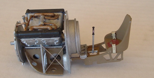
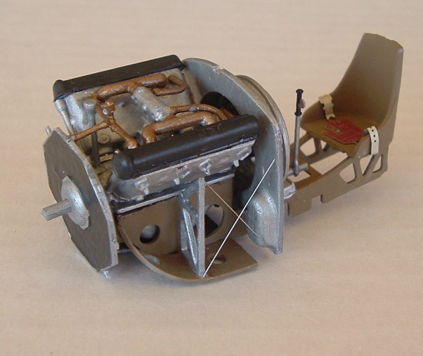
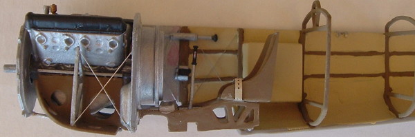
Because I didn't know the engine would cause a fit problem, I proceeded to build it in Steps 3 through 8. An instruction erratum packed separately from the instructions advised against using Parts 8Z, 9Z, 18Z, 19Z and 23Z. Therefore, I left these parts off. If you do not intend to put the engine in your model, you should consider building it to be displayed separately. It's very nice. The only problem I noticed was that the round tabs on the cylinder cases did not fit into the locating holes designed to receive them. I wasn't too concerned about a good fit here, but if you intend to display the engine separately, you will need to come up with a plan to fix this issue.
The instructions call for a rather monochromatic painting of overall aluminum engine with some copper piping. If nothing else, my research indicates that the at least the cylinder heads (Part 23Z) need to be painted a black or dark metal color. In some photos of this type of engine, both cylinder cases are painted in this manner.
Steps 9 through 11 deal with the cockpit interior. Be aware that the instructions call for painting the engine support brackets (Part 9D) wood, when they should be aluminum. I added colored French Seat Belts from Eduard. Also in this part of the model I added the instrument face decals to the instrument panel. Unfortunately, this was the only part of the Roden decal sheet that was out of register. With some deft trimming and painting, I attempted to overcome this issue.
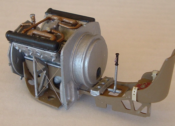
 I assembled the machine gun and set it aside until the end of the project, using it to help place the instrument panel (Part 1E) and firewall (Part 47A) in their proper places in the fuselage. The engine and radiator are added next. I found it helpful to attach the radiator to the engine before attaching the engine support yoke (Part 27A) and the final pipes to the engine (Parts 31A and 7Z).
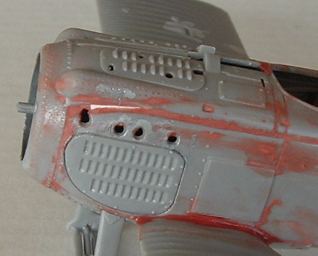
After this, I proceeded to assemble the undercarriage, close up the fuselage and add the empennage. It was at this point where I realized the engine would not fit – even when I removed parts 23Z per the errata. Therefore, I removed the cylinder cases (which weren't glued on too well due to the fit problem I mentioned earlier). Even so, I still had some considerable gaps in the forward fuselage area. Because this area has some pretty fine detailing, I knew I wouldn't be able to do much sanding. After slipping in some strip styrene to fill some gaps, I liberally used some Bondo putty evened out with a cotton bud (Q-Tip) soaked in acetone. I used a small, fine-grained scrap of sandpaper to smooth over the rough parts that remained. I didn't lose one rivet or mangle any raised louver. I assembled the exhaust pipes, but set them aside for assembly with the machine gun. I test fitted them and had to remove some plastic with a sharp knife to insure they would set into the fuselage correctly.
 Now comes the part that intimidates many modelers – fitting the wings. Actually, this part of the process went a lot better than previous steps. While the lower wing practically snaps into place, Part 49A, which looks like the lower part of a gasoline tank, requires a little trimming to fit into the fuselage. Then I attached the undercarriage (without the wheels) and the cabane struts.
At this point, I painted the portion I had already assembled to this point, as well as the top wing. The fabric areas received PolyScale Clear Doped Linen, while the metal parts on the forward fuselage received Gunze-Sangyo Sandy Brown. These are just my choices based on an opinion developed by studying black and white photos, reading various World War I references and discussing the subject with members of the World War I Mailing List. In the past I have used Humbrol Matt Linen with Tamiya Dark Yellow. And I may use a completely different combination on another model sometime in the future.
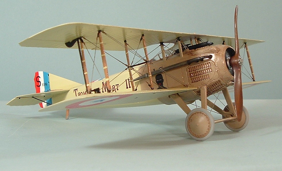 I painted almost all the rest of the smaller parts, too. The interplane struts are mostly ModelMaster Wood with PolyScale Clear Doped Linen straps (which are molded onto the struts) and black hardware. This is something else I deduced from photographs – particularly of Guynemer's mount displayed at the Musee de l'Air in Paris All the metal bits — aileron actuating mechanism, the bar attaching the rigging bracing struts and even the metal attachment points for all the struts — appear to be japanned (painted over with black enamel).
When the paint dried, I drilled out all the holes where I intended to insert my rigging wires. The instructions provide a fairly detailed schematic for the rigging with darker lines used to indicate where dual wires are required. The schematic is not sufficient for attaching all the wires in the cabane strut area. I would recommend the Aviatik Book for specific photos of the area as well as the photos posted on the World War I Modeling Page.
 Once the drilling was accomplished, I was ready to attach the upper wing. First I glued the upper wing to the cabane struts that were already attached to the fuselage. I scraped away the paint and used a gel-type plastic cement to get the best bond possible for this attachment on bare plastic for both the fuselage and the upper wing. Then I let it dry for 24 hours. It was then very easy to snap the interplane struts into their proper locating holes. I used a small amount of CA glue for this procedure. Check the instructions to make sure you position all the struts so that the molded-on turnbuckles are facing in the correct direction.
At this point the model received an overall coat of Tamiya Clear Gloss. After this dried, the decals were applied. Each decal was applied over a generous puddle of Micro Sol, which allowed for a few very quick minor adjustments to alignment and positioning. For those decals applied over raised details, I used generous applications of Solvaset. Once the product had a chance to soften the decal, I used a cotton bud soaked in Solvaset to press down on any bubbles. The only place this technique didn't work was on the rudder.
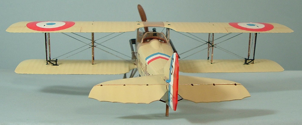
 Both the SPAD VII and XIII have a relatively huge rudder control cable fairing molded on each side of the rudder. On smaller scale models I have been able to coax decals to settle over the fairing. But it is just too large in 1/32 to be able to expect to get a decal to expand and cover it. It may be possible to cut the decal allowing the fairing to protrude through. However, this would require finding a perfect paint match for the decal color. In my experience this is rather difficult because the shade of paint is always either just a little darker or a little lighter than the shade of the decal. This is a problem when you are applying the paint directly adjacent to the decal. But if there is some distance between the paint and the decal, you can fool the eye into interpreting both colors being identical. Which brings me to my solution.
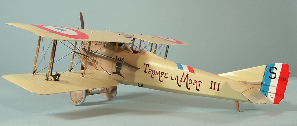
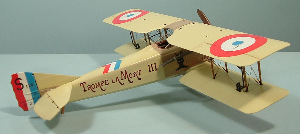
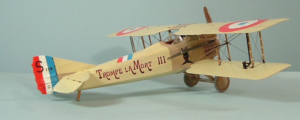
First, I painted the rudder an overall gloss white. Next, I measured the width and found it to be 20 millimeters. When dry, I cut a strip of masking tape 5 mm wide and applied it down the center of the rudder. Then I masked off the scalloped end and sprayed on Gunze-Sangyo Sky Blue. When that dried, I masked off the Sky Blue and painted the scalloped end ModelMaster Italian Red. These colors are close enough in shade to the decals – and far enough away from them physically – to fool the eye into thinking they are the exact same color. Of course, I'm colorblind, so I could be completely wrong. Judge for yourself from the pictures.
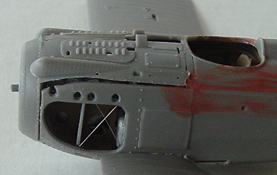
 This solved one of the three big challenges of building a SPAD fighter. You may remember the other two were the louvers and the rigging attachments to the interplane bracing struts. For the louvers, I applied an acrylic wash of Ceramcoat Burnt Sienna to the louvers with a narrow flat brush. When it dried, I went over the raised detail with a damp cotton bud to remove some of the wash. I'm not real satisfied with the result, but decided to keep going in order to finish this review in a timely manner.
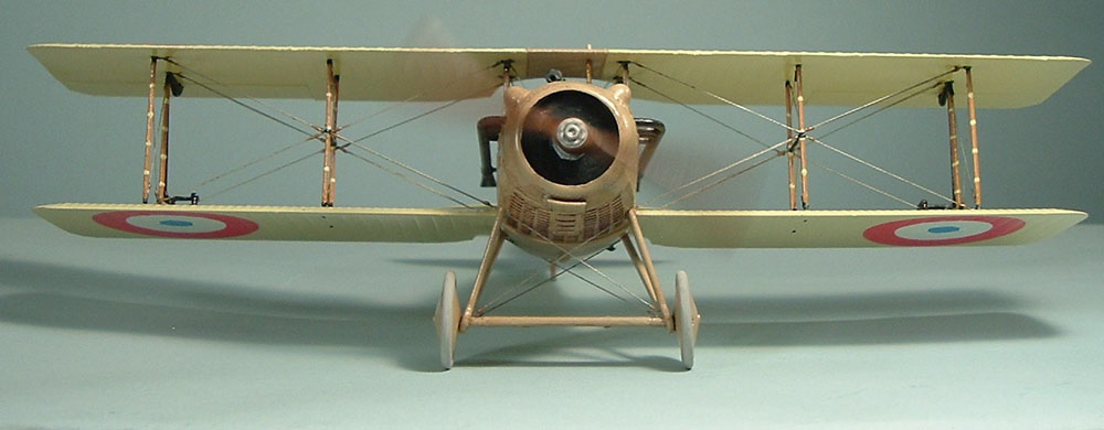
I addressed the issue of the interplane bracing struts the same way I have in my 1/72 and 1/48 builds. I have noticed that many people simply run the interplane rigging from the top cabane strut all the way to the bottom of the bottom of the outer interplane (or from the lower fuselage to the upper interplane strut) without attaching the wire, invisible thread, heat-stretched sprue or tippet line to the bracing struts. But if you look at actual photos, you will see that the rigging attaches to the bracing strut, not in front of it and not through it. I've provided side-by-side shots of the real thing (from a photo on the World War I Modeling Page) and the model I built to illustrate what I mean.
Some of the struts have rigging hardware already attached and it is a simple matter to glue the wire to these attachment points. I used .008 diameter stainless steel wire available from Small Parts, Inc. The remainder of the rigging was placed into the holes I drilled earlier in the build. The wire seemed too shiny for my taste on this particular model, so I painted them all in ModelMaster Steel. Then I replicated the turnbuckles with a minute glob of aged Pactra Brass. Once again, I wasn't all that pleased with the result and will probably try something different on later 1/32 builds.
After the kit was fully rigged out, I applied another overall coat of Tamiya Gloss. When that dried, I sprayed on ModelMaster Semi-Gloss. I completed the model my adding the windscreen, wheels, machine gun, propeller and exhaust pipes.
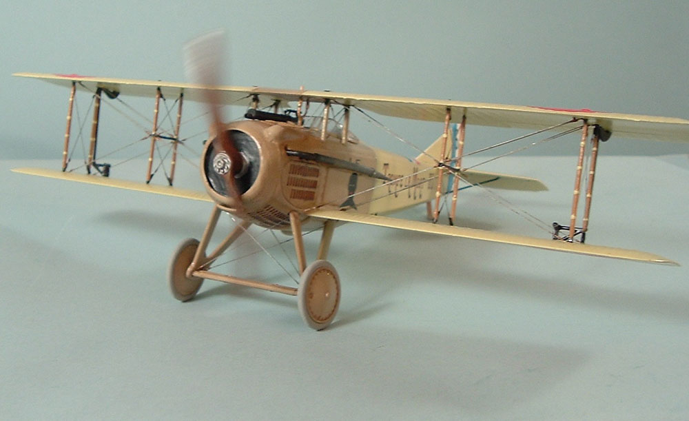
 These last two parts require some detail on the painting techniques I used. Most photos I studied indicated that SPAD propellers were of a uniform tone – meaning to me that I shouldn't use a painting technique that represented the lamination of different colored wood. Therefore, I painted the part with Humbrol Natural Wood overall, then used Burnt Umber oil paint to represent the wood grain. I just put a dab of oil paint on a propeller face, and then wiped a cotton bud from the hub to the propeller tip several times until I got the result I sought. I think in the future, I will use a lighter base – ModelMaster Wood.
The exhaust pipes began with an overall coating of ModelMaster Steel. Then I brushed on ModelMaster Metalizer Burnt Metal. After that, in a few places where heat build-up was greater, I applied ModelMaster Metalizer Burnt Iron. After buffing up the Metalizers, I dry-brushed ModelMaster Jet Exhaust in a couple of areas for highlights. I'm very pleased with the result.
Conclusion
I've built several SPAD VIIs in two other scales and by four different manufacturers. I'd have to say that this was the best of the lot. I think it takes this scale to adequately convey the delicacy of World War I aircraft.
I'm not one that likes my kits to just fall together. Heck, I even manage to make Eduard kits difficult. This kit has just enough challenge to it to make it an interesting build, but doesn't require any major surgery or aftermarket parts to make a complete model. I do wish that the little triangles (Part 15D) for the aileron actuating mechanism were thinner. They way they are now make it impossible to apply the bracing wire through them correctly.
I was somewhat disappointed that the engine didn't fit and would have preferred building it outside the airframe to be displayed separately. However, please note that if you want to build the model with the engine exposed, don't plan on leaving off the top two parts of the cowling (3A and 4A). First, the forward cabane struts attach to these parts. Second, from my study of contemporary photos, I don't think the panels detached from the fuselage the way that they are molded.