


 Revell
1/35 MARS rocket launcher
Revell
1/35 MARS rocket launcher
by Juho Ala-Jaaski
History
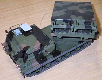
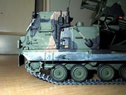
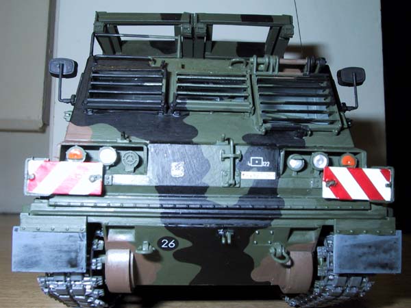
The MARS launcher is a German upgraded version of the American MLRS launcher which is based on the M2 Bradley chassis. The German version includes sideskirts and mud flaps, rocket blast covers when the transport is on the move, an added pair of antennas on the right side of the cab, red and white striped plates for the cab corners and the back of the launcher and the German ID tag on the rear bumper.
The German army started using the MARS in 1990. The launcher takes twin six-packs of either 277mm M77 rockets with 644 mini-bombs per rocket, or 237mm AT-2 mine rockets with 28 Antitank-mines per rocket. It has a maximum firing range of approximately 39.000 meters (127,952 feet). It has a semiautomatic loader which can load the MARS within a few minutes.
 The
MARS is driven by a 508hp. VTA-903 diesel engine with a max. road speed
of about 64km/h.(39miles) It carries a three man crew.
The
MARS is driven by a 508hp. VTA-903 diesel engine with a max. road speed
of about 64km/h.(39miles) It carries a three man crew.
The kit
The kit is molded in four different shades of green with seven sprues, with vinyl track parts, decals and window screens in clear acetate (these were missing in my kit, so I had to make new windows). One of the track parts was warped on my sample so I had to straighten it out.
The track pattern looks different from a Bradley, so I don't know if this is correct.
The kit fits together OK, but the cab and launcher sides are hard to align. You have the option of gluing the window slits open or closed, and posing the driver's window screen, doors, door windows, and roof hatch open. You can also leave the launcher to rotate and elevate. Locking arms are provided if you want to pose the launcher in the firing position. No crew figures are provided. The interior of the cab is nicely detailed.
I'm going to go through this step by step again, as I find that the best way.
Lower hull (Step 1)
 In
this step you attach the road wheels. Be careful aligning them as they're
easily bumped to some other direction. It's easy to get all to touch the
ground though. The shock absorbers are provided as separate parts.
In
this step you attach the road wheels. Be careful aligning them as they're
easily bumped to some other direction. It's easy to get all to touch the
ground though. The shock absorbers are provided as separate parts.
The backs of the roadwheels have no detail at all and each one has two (2 have four) ejector marks on the backs, these are in a groove so they're almost impossible to sand out.
I painted everything dark green and the road wheel rubber portion with flat black. The drive sprocket teeth and the part of the idler wheel that touches the track were painted with dull silver to simulate wear. The drive sprockets were supposed to be attached at step 3 but I attached them already, and the same goes for the return rollers. I also attached the track at this point.
Lower hull frontplate (Step 2):
In this step you attach the drive train covers and the front tow hooks. Everything went well. These were all painted the surrounding camo color.
Steps 3 & 4:
All the parts of these steps were already installed as I felt that was easier.
Cab radio (Steps 5,6 & 7):
 Now
you make the radio for the inside of the cab. Everything fit well, and
the shelves were painted the interior color of light bluish grey, the
radios were painted black with white, silver and red dials. The walls
were painted with the interior color also. The seat cushion was painted
red brown with a green back.
Now
you make the radio for the inside of the cab. Everything fit well, and
the shelves were painted the interior color of light bluish grey, the
radios were painted black with white, silver and red dials. The walls
were painted with the interior color also. The seat cushion was painted
red brown with a green back.
The driver's side console was painted black with white dials, and a light grey base. The seat legs were painted with the interior color of light bluish grey (known as light grey from now on). The exterior hooks were put on after the cab had been put together. The foot pedals were painted silver.
Cab front (Steps 8,9,10 & 11)
These steps involve the front wall of the cab. I decided to glue the window slits in the open position, but the driver's window slits were left open with the hatch itself in the closed position. These were attached first, and then the two grab handles on top of them Along with the headlight tops. The headlights were glued on after filling all the sinkholes that marred the faces of all of them and painting. Luckily, the horn didn't have a sinkhole on it or it would have proven almost impossible to fill!
 I
put on the windscreens at this point which I made from clear acetate.
I put them on before the window slits were glued on to make assembly easier.
You also have to choose whether you want the driver's window slit hatch
openable or not. I glued it in place. All the parts were painted with
the surrounding camo color with silver for the headlights and orange for
the turn signals.
I
put on the windscreens at this point which I made from clear acetate.
I put them on before the window slits were glued on to make assembly easier.
You also have to choose whether you want the driver's window slit hatch
openable or not. I glued it in place. All the parts were painted with
the surrounding camo color with silver for the headlights and orange for
the turn signals.
Steps 12 & 13
These steps involve the cab front wall interior. This was painted with the same light grey as the rest of the interior. You're actually supposed to glue the windscreens on now, but I already did that. The instrument panel was painted black with a dark grey housing and white instrument faces, and white and red knobs. The missile guidance apparatus was painted black with white knobs and a light grey base. The steering "wheel" was painted green with grey handles and the stick in between the two instrument panels was painted grey.
Cab doors and sidewalls (Steps 14, 15, 16 &17)
 In
these steps you make the cab doors and sidewalls. The interiors of all
were painted with the interior color - light grey, and the outsides with
the corresponding camo colors. The doors and the door windows were glued
shut with the vision slit screens made from clear acetate. The window
latches fit poorly so that's one of the reasons why I had to glue them
shut.
In
these steps you make the cab doors and sidewalls. The interiors of all
were painted with the interior color - light grey, and the outsides with
the corresponding camo colors. The doors and the door windows were glued
shut with the vision slit screens made from clear acetate. The window
latches fit poorly so that's one of the reasons why I had to glue them
shut.
Cab roof (Steps 18 & 19)
These two steps involve the cab roof. The interior was painted with the same interior color as the rest of the interior walls, with the seals around the hatch painted black along with the different computer parts. The launch button was painted red and the rest of the dials white. The roof hatch fit poorly again. I glued it in the open position to allow a better view of the interior. The exterior was painted with the surrounding camo colors. I also skipped the next step as I already glued all the cab components together at this point. The parts didn't fit together too well, so I had to fill and sand the seams here and there. I accidentally left of the two decals that were supposed to go on the inside surfaces of the doors, but they wouldn't have shown too much anyway!
Engine compartment (Steps 21,22 & 23)
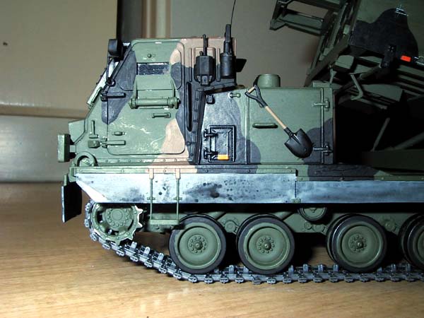
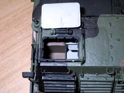
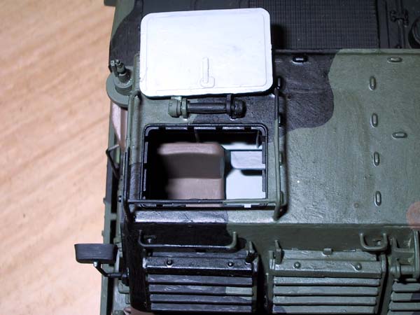
In these three steps you make the engine compartment. Everything fit together well, and all the parts were painted with the surrounding camo color, except for the shovel which was painted black with a brown handle.
Steps 24 & 25:
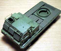 In
these two steps you only assemble three parts and glue the hull halves
together. Use tape to hold the hull halves together when the glue dries.
I already assembled and put on the tracks so they weren't of course added
in this step as they were supposed to. The three parts you assemble in
these steps are two what appear to be some kind of hook mounts and and
one that appears to be some kind of a cover for something. Everything
fit well again and all the parts were painted with the surrounding camo
color, which in this case was dark green as the bed isn't camouflaged.
In
these two steps you only assemble three parts and glue the hull halves
together. Use tape to hold the hull halves together when the glue dries.
I already assembled and put on the tracks so they weren't of course added
in this step as they were supposed to. The three parts you assemble in
these steps are two what appear to be some kind of hook mounts and and
one that appears to be some kind of a cover for something. Everything
fit well again and all the parts were painted with the surrounding camo
color, which in this case was dark green as the bed isn't camouflaged.

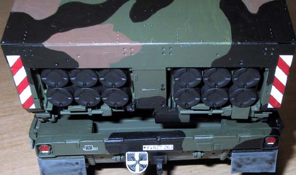
Hull rearplate (Steps 26 & 27)
These steps involve the hull rearplate. I left the tow cable off, for no good reason though. Everything fit well, and all the parts were painted with the surrounding camo color, except for the lights which were painted red with small white reflectors.
I had to pin down the backplate with some tape and laundry pins while the glue dried.
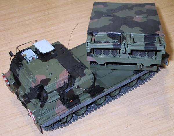
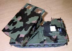
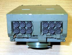
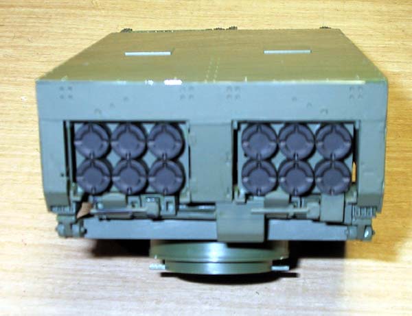
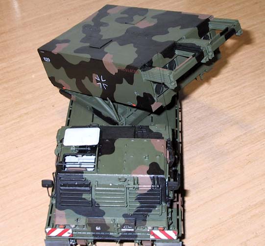
The launcher(steps 28-37)
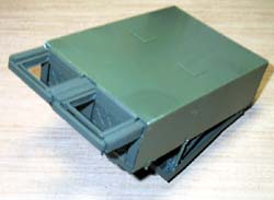 The
construction of the launcher starts with the simple superstructure frame.
The inside of the launcher components were painted dark green. I added
a piece of styrene sheet to the lower superstructure to block the view
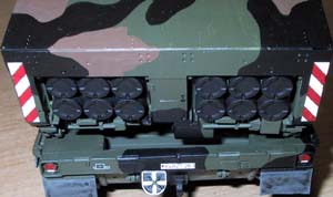
into the launcher. Only the ends of the two six-pack rockets are provided.
The ends of the rockets were painted flat black.
The
construction of the launcher starts with the simple superstructure frame.
The inside of the launcher components were painted dark green. I added
a piece of styrene sheet to the lower superstructure to block the view
into the launcher. Only the ends of the two six-pack rockets are provided.
The ends of the rockets were painted flat black.

You have the option of leaving the elevator arms moveable, which is what I did. Locking arms are provided if you want to pose the launcher in the UP position. If you choose the down position, leave the sliders off the elevator arms.
The rocket loading rails didn't fit too well, so I had to fiddle with them quite a bit.
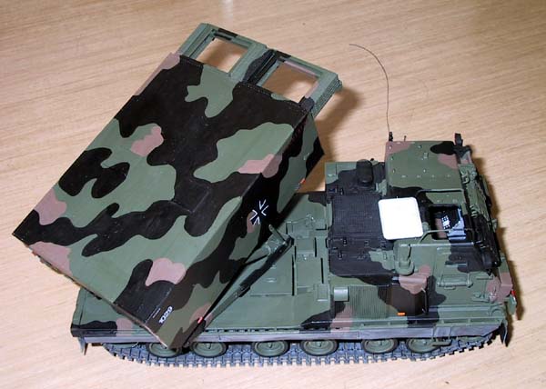
You can assemble almost the whole launcher assembly before having to worry about painting
 The
outsides of the launcher were painted with the corresponding camo colors
of black, red brown and dark green. The reflectors on the sides were painted
orange and the elevator arm sliders were painted silver.
The
outsides of the launcher were painted with the corresponding camo colors
of black, red brown and dark green. The reflectors on the sides were painted
orange and the elevator arm sliders were painted silver.
Launcher base assembly (Steps 38 & 19)
Now it's time to make the base for the launcher. If you want to leave the launcher elevatable, then don't glue the hinges or elevator arm attachments to their attachments, get it? I glued all the parts on before painting (except for the launcher to it's mounts) Everything was painted dark green again.
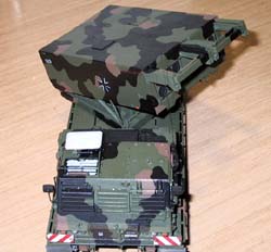
German version conclusion (Steps 40 & 41)
In these steps you attach the following parts unique to the German version: side skirts, mud flaps, roof hatch frame, extra antenna, ID stripe plates, launcher exhaust covers, and the NATO crossplate. I didn't use the exhaust cover plates as my model's launcher is in the ready position. I painted the ID stripe plates white so that the decals would not be translucent once applied. I also painted the white cross on the NATO plate instead of using the decals that come with the kit. The side skirt were painted grey with a black wash.
 Painting
and decals
Painting
and decals
The model was painted in the standard German army camo of red brown, black and dark green. I used Tamiya acrylics and Revell-Germany enamels.
For the markings I chose one from the 4.BATTERIE/RAKETENARTILLERIEBATAILLON based in Germany during August 1995 named POCULATOR.
All the markings went on with out a hitch and no silvering occurred either! Revell has finally fixed their decals! Weathering was accomplished with a little pastel chalk on the side skirts and lower hull.
Thanks to TIETO-NIKKARI, Helsinki, Finland for the review sample. Check out their webpage !!!


Previous: Contents

