 Building
VLE Models' 1/72 DFW 'Mars'
Building
VLE Models' 1/72 DFW 'Mars'
Biplane Version
by Michael Kendix
Introduction
In its early days, the Deutsche Flugzeuwerke (DFW) company produced copies of Farmans and Nieuports; the 'Mars', first built in 1912, was an original design. The title 'DFW Mars' was applied to two biplanes and a monoplane. The manufacturing process permitted flexibility to produce either the monoplane or biplane versions, both having the same undercarriage, tail and fuselage. The 'Mars' was used in 1912 and 1913 during the Balkan wars and one was purchased by Britain in 1913. In 1912 , a 'Mars' was assembled at Brooklands in England and in 1914 one was purchased by the Royal Naval Air Service (RNAS) and given the number '154'. It was stationed at Eastchurch,but when the war broke out it was moved north to Immingham since it was thought a bad idea to have a German machine operating in southern England at that time.
In August 1914, while on its flight north, a minor problem forced it to land at Scarborough race course, presumably much to the amusement of the local populace. An excellent historical review of the DFW 'Mars' was written by Harry Woodman in Airfix Magazine, March 1982.
 An
in-box review of this kit appeared in a previous issue of Internet Modeler.
In addition to the single vacuformed sheet, the kit contains several metal
parts, pieces of plastic rod, photoetch wire wheels and other small odds
and ends. In terms of quality, the parts and the vacuformed sheet are
at the high end; the vacuformed sheet is well detailed and crisp, the
metal propeller is finely made and the other parts are fairly well done.
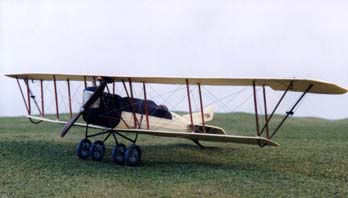
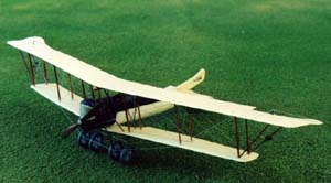
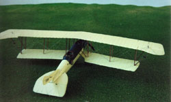
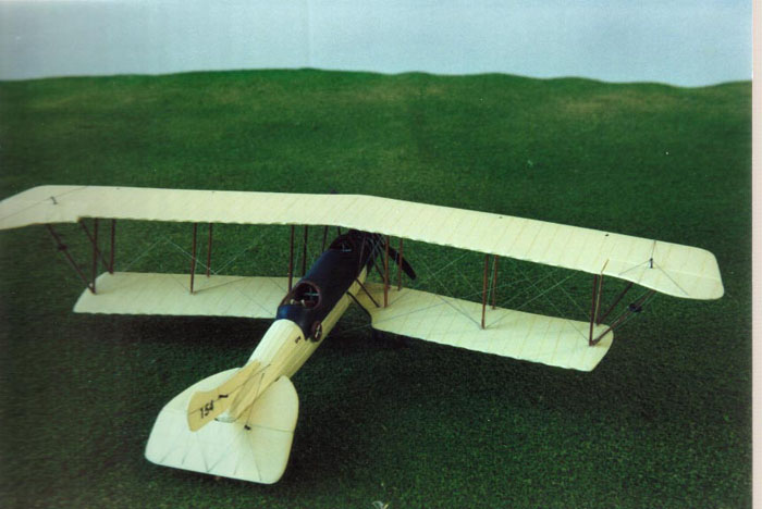
The kit permits you to build a monoplane or biplane version; I decided
to build the biplane version, specifically, RNAS '154', which is shown
on page 322 of Airfix Magazine, March 1982.
An
in-box review of this kit appeared in a previous issue of Internet Modeler.
In addition to the single vacuformed sheet, the kit contains several metal
parts, pieces of plastic rod, photoetch wire wheels and other small odds
and ends. In terms of quality, the parts and the vacuformed sheet are
at the high end; the vacuformed sheet is well detailed and crisp, the
metal propeller is finely made and the other parts are fairly well done.
The kit permits you to build a monoplane or biplane version; I decided
to build the biplane version, specifically, RNAS '154', which is shown
on page 322 of Airfix Magazine, March 1982.
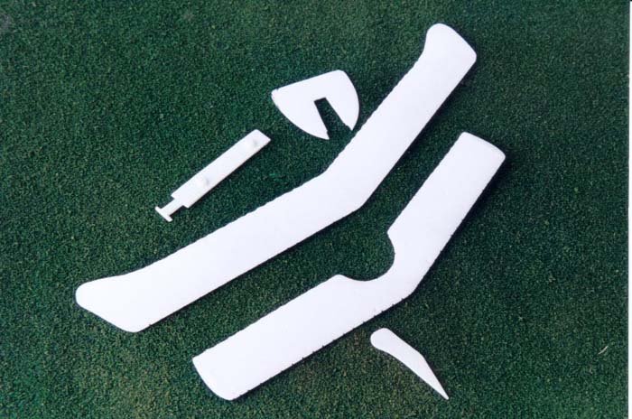
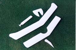
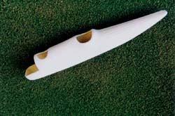
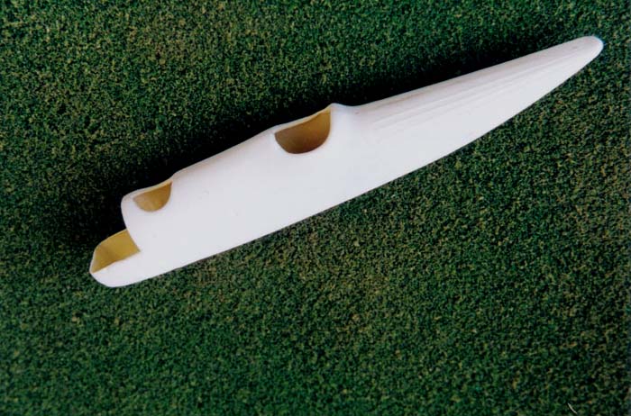
The vacuform sheet is quite thin, which is ideal for aeroplanes of this era, whose wings are translucent. I drew around the vacuform parts on the sheet, using a black marker to provide a guide for cutting. I would recommend that you use a lighter colour since the thinness of the plastic and the light colour of the model, eventually made it difficult to cover the black marker pen marks.
The Cockpit
As usual, I began construction with the cockpit interior. The kit provides a vacuformed floor, four bulkheads and two seats. The instruction sheet advises you to construct and seal the fuselage halves, and then build up the cockpit contents, including the bulkheads for which slots are cut into the floor. You are then instructed to slide the entire assembly into the cockpit area via the engine firewall. I attempted this but would advise against it. There is no guarantee that the bulkheads are going to be correctly positioned; they need to be at the engine wall, instrument panel, between the two seats and then a bulkhead behind the rear seat. Mine did not line up and I had to break open the fuselage. I then proceeded in the more orthodox way, gluing the interior contents to the fuselage sides and then closing up the fuselage.
The interior is limited to a control wheel, the bulkhead/instrument panel and seats. I added seatbelts using thin tape but the latter is purely conjectural. I also added internal stringers, which were all hidden by the cockpit floor. The fuselage interior was painted clear-doped linen (CDL) for which I used Polyscale Aged White. I added some detail to the instrument panel; details varied significantly, so I just used the details that are molded on the kit part. Fuselage, lower wing and tail parts
 After
completing the cockpit interior, I painted the engine 'Engine grey' and
then dry-brushed it with aluminium. I closed up the fuselage and put on
the radiator housing. Unfortunately, the kit's fuselage halves were of
unequal length. I compromised at this point, adding some putty and filing
down the longer half until they were of equal length. The fuselage join
seam and the seam for the radiator housing were then puttied and sanded.
It took several efforts to make a smooth join for these.
After
completing the cockpit interior, I painted the engine 'Engine grey' and
then dry-brushed it with aluminium. I closed up the fuselage and put on
the radiator housing. Unfortunately, the kit's fuselage halves were of
unequal length. I compromised at this point, adding some putty and filing
down the longer half until they were of equal length. The fuselage join
seam and the seam for the radiator housing were then puttied and sanded.
It took several efforts to make a smooth join for these.
During the fuselage joining and sanding process, the stringers were sanded off and needed replacing. I used 1/64th inch Chart Tape that I simply cut to length and stuck to the surface directly over the fuselage join, covering up any hint of a seam. The tape is black and proved to be hard to cover with the CDL.
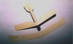
After removing the lower wing from the sheet, the underside ribs were scribed into the surface. Using an X-acto knife I cut two parallel lines approximately 1/64th inch apart for each rib position.
 When
gluing the lower wing, a number of factors need to be born in mind. First,
there is a dihedral for the lower wing but not the upper. Therefore, when
you make the interplane struts, they have to be shorter on the outside.
Second, you need to dry fit the lower wing and landing gear legs to ensure
that the latter will fit when the lower wing is in place. Third, there
is no obvious means to attach the lower wing to the fuselage. I simply
drilled two holes through the wing and fuselage and used .020" plastic
rod to attach it. You need to leave a space between the wing and the fuselage
(the rod will show) in order to create the dihedral.
When
gluing the lower wing, a number of factors need to be born in mind. First,
there is a dihedral for the lower wing but not the upper. Therefore, when
you make the interplane struts, they have to be shorter on the outside.
Second, you need to dry fit the lower wing and landing gear legs to ensure
that the latter will fit when the lower wing is in place. Third, there
is no obvious means to attach the lower wing to the fuselage. I simply
drilled two holes through the wing and fuselage and used .020" plastic
rod to attach it. You need to leave a space between the wing and the fuselage
(the rod will show) in order to create the dihedral.
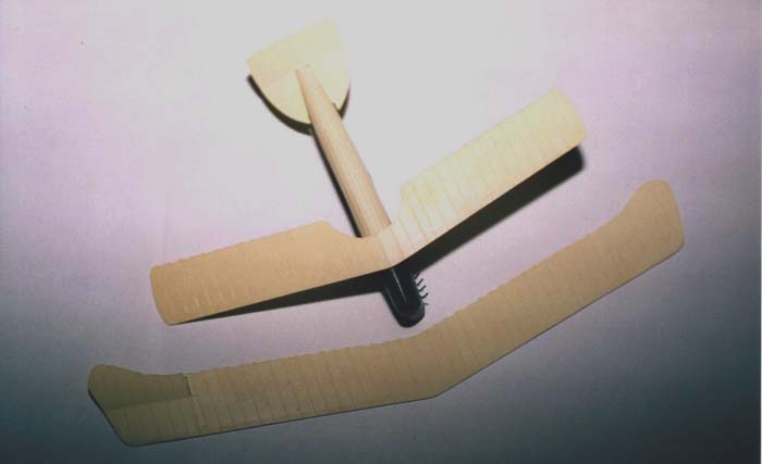
The tail parts were cut out of the vacuform sheet and the obverse sides were appropriately scribed for the ribs. I cut off the tail elevator and reattached it at an angle. The horizontal parts were attached using a similar approach to the lower wings, except I used copper wire for the rods.
 The
entire sub-assembly, that is, wing, fuselage and tail, was then painted.
First, I sprayed the forward fuselage Scale Black, and then I masked this
off and painted the remaining parts CDL. It took a fair amount of touch
ups to ensure the black chart tape and the black pen cutting guideline
marks were covered. The radiator grille was painted a brass colour and
a Crayola washable marker was used to 'wash' it.
The
entire sub-assembly, that is, wing, fuselage and tail, was then painted.
First, I sprayed the forward fuselage Scale Black, and then I masked this
off and painted the remaining parts CDL. It took a fair amount of touch
ups to ensure the black chart tape and the black pen cutting guideline
marks were covered. The radiator grille was painted a brass colour and
a Crayola washable marker was used to 'wash' it.

Finally, I added the six exhaust pipes to the engine. These are made from thin lead solder wire. There is plenty provided but I did not cut the correct lengths initially, however, my local Radio Shack store sold me a whole roll of the material; enough for a lifetime and not expensive.
The Upper Wing
 The
upper wing is well detailed and came out nicely from the vacuform sheet.
I detailed the underside in the same way as the lower wing and cut away
the aileron control surfaces. The next task was to make the twelve interplane
struts. You can use the plastic strut material provided in the kit, however,
I find this material a little flimsy and prefer to use bamboo. Bamboo
is strong and has a wood grain that is ideal for early aeroplanes. I used
the method explained in a previous Internet Modeler article (Phönix D.III)
and then proceeded to glue on the top wing. I took the four inner most
interplane struts and glued them to the upper wing. Then, using a jig
made from audiocassette tape boxes, I jigged it up and glued it to the
lower wing. After that dried, I added each of the interplane struts, working
from the inside to the out side, and trying to maintain the dihedral on
the lower wing; the upper wing has no dihedral. I then added the various
cabane struts and the out diagonal sloped struts using .020" plastic rod.
The
upper wing is well detailed and came out nicely from the vacuform sheet.
I detailed the underside in the same way as the lower wing and cut away
the aileron control surfaces. The next task was to make the twelve interplane
struts. You can use the plastic strut material provided in the kit, however,
I find this material a little flimsy and prefer to use bamboo. Bamboo
is strong and has a wood grain that is ideal for early aeroplanes. I used
the method explained in a previous Internet Modeler article (Phönix D.III)
and then proceeded to glue on the top wing. I took the four inner most
interplane struts and glued them to the upper wing. Then, using a jig
made from audiocassette tape boxes, I jigged it up and glued it to the
lower wing. After that dried, I added each of the interplane struts, working
from the inside to the out side, and trying to maintain the dihedral on
the lower wing; the upper wing has no dihedral. I then added the various
cabane struts and the out diagonal sloped struts using .020" plastic rod.

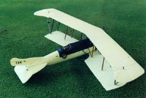
Some photographs show little wheels on the wing extension struts, which are part of the wing-fold mechanism. The picture of 'RNAS 154' appears to show these 'wheels' although my copy is a little blurred. Regardless, I added these onto the wings' structure. Unfortunately, I had already glued these extension struts so I dismantled them and placed a small plastic disk with a hole onto each strut. A series of eight wires was then attached from the wing to each of these disks.
Landing Gear and Final Construction
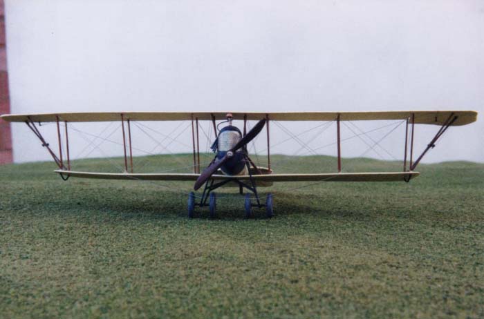
 The
landing gear have to carefully dry-fitted before gluing since they will
not fit if they are not the correct length and the lower wing is not correctly
positioned. The kit contains hollow wire to build the landing gear legs,
however, they are thick and I used thin piano wire to replace them. The
kit contains a set of photoetch wheel spokes and wheel halves to construct
the spoked wheels. I used some rubber O-rings to replace the wheel halves
and simply glued the photoetch spokes to each side of the O-rings. After
painting the O-rings medium grey and the spokes aluminium, I attached
them to the axle made from plastic rod; the same material I used to make
the remaining landing gear struts. I used a combination of bamboo and
plastic rod to make the tailskid.
The
landing gear have to carefully dry-fitted before gluing since they will
not fit if they are not the correct length and the lower wing is not correctly
positioned. The kit contains hollow wire to build the landing gear legs,
however, they are thick and I used thin piano wire to replace them. The
kit contains a set of photoetch wheel spokes and wheel halves to construct
the spoked wheels. I used some rubber O-rings to replace the wheel halves
and simply glued the photoetch spokes to each side of the O-rings. After
painting the O-rings medium grey and the spokes aluminium, I attached
them to the axle made from plastic rod; the same material I used to make
the remaining landing gear struts. I used a combination of bamboo and
plastic rod to make the tailskid.
I printed the '154' and 'DFW'decals on decal paper using an LaserJet H.P.IIIp I made the aileron control horns from plastic card and the rigging from .005 inch straight stainless steel wire from Smallparts. I did a poor job of cutting out the fuel tank from its pour block so I replaced it with thick plastic rod.
Conclusion
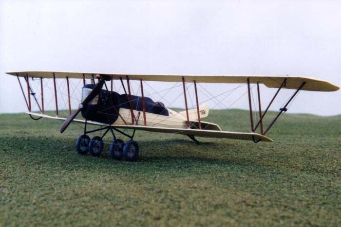
 The
foregoing description of my building this kit is somewhat truncated in
terms of actual events. My usual time for a biplane is approximately one
month, however, this took me more than double that time. Naturally, the
fact that it was a vacuform kit adds to the time, not only because I had
to cut out the parts from the plastic vacuformed sheet but the kit required
a significant amount of scratch building (landing gear, struts, fuel tank,
etc.). Further, I made a number of mistakes that extended the length of
the project significantly. The kit is not for beginners, but it is unique
and if you have a modicum of patience and determination, it is possible
to build an unusual and attractive model from the early era of flight
history.
The
foregoing description of my building this kit is somewhat truncated in
terms of actual events. My usual time for a biplane is approximately one
month, however, this took me more than double that time. Naturally, the
fact that it was a vacuform kit adds to the time, not only because I had
to cut out the parts from the plastic vacuformed sheet but the kit required
a significant amount of scratch building (landing gear, struts, fuel tank,
etc.). Further, I made a number of mistakes that extended the length of
the project significantly. The kit is not for beginners, but it is unique
and if you have a modicum of patience and determination, it is possible
to build an unusual and attractive model from the early era of flight
history.
Acknowledgment
I am most grateful to Bob Wheeler for answering my numerous questions during this kits construction. Len Smith was most helpful in providing references. Finally, I would like to thank Knut Erik Hagen for some outstanding photographs of the Mars taken by Commander Thommesen.
Reference
Harry Woodman, 'The First German Aeroplane to Go to War' Airfix Magazine, March 1982, pages 318 to 324.


