Classic Airframes 1/48 Lockheed Hudson Mk.IBy Michael Benolkin | 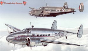 |
History
The Hudson started life as the Lockheed Model 14 Super Electra and was designed to compete in the civil aviation world against the new series of Douglas DC-X aircraft. The Model 14 was designed to operate with a variety of powerplants including the Wright Cyclone, Pratt & Whitney Twin Wasp and the Pratt & Whitney Hornet. The prototype Model 14 first flew in July 1937, powered by the P&W Hornet.
 As war was approaching in Europe, the RAF sought out aircraft that it could press into service almost immediately. The Model 14 was adopted with some modifications as the Hudson, first flying in December 1938. Thousands of Hudsons were produced between 1939 and 1943, with examples delivered to Great Britain, Australia, New Zealand, Canada, the Netherlands, China and the United States.
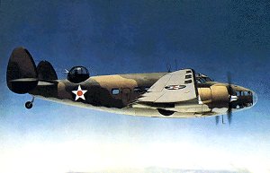
There were a number of variants of the Hudson. In British and allied service, there were the Marks I - V which were designed as patrol bombers and reconnaissance aircraft. All were equipped with a Boulton Paul dorsal turret and differed primarily in engine and propeller combinations. The Mark VI was designed as a transport version of the Hudson with the dorsal turret deleted.
In US operations, the Mark IIIA version (which was a Mark III with bench seats installed) served as the A-29 by the USAAF and as the PBO-1 by the USN. A transport version was also designated as the C-63. The Mk.VI transport version was also adopted as the A-28.
Two unique versions of the Hudson were also produced for the USAAF: the AT-18, which had a Martin dorsal turret in place of the Boulton Paul, which served as a aerial gunnery trainer; and the AT-18A, which had a US-styled bombardiers nose with the Norden bombsight installed for bombardier training.
Among the most notable historical tid-bits in the Hudson's operational history, it has the distinction of being the first US-built aircraft to achieve an aerial victory in WW2. Another incident involved a RAAF Hudson that was discovered by a flight of six A6M2 Zeros, one of which was flown by ace Saburo Sakai. While the average dogfight lasts less than a minute, what transpired here was simply amazing - you can read about the incident at the site Hell is a Hudson.
The Kit
The Classic Airframes Hudson Mk.I kit consists of 67 light gray and 28 clear injection-molded plastic parts for everything but the aircraft interior. The interior is comprised of 35 nicely molded resin parts. This kit provides all of the parts for a standard Hudson Mark I as well as the civilian version, the Lockheed Model 14. There are only a few parts not used for either version, as many of these parts trees are common to the upcoming later Mark Hudson kits. The styrene has only a minimal amount of molding flash on the trees and no injector pin marks in visible locations.
Preparation
The trick to a trouble-free build of this (or any other) kit is preparation. The first step was to study the instructions and get a feel for where any surprises might lurk. One of the advantages of armor building is gaining the sense of subassemblies where different parts of the kit can be built in parallel without later complications. I decided how to do the same with the Hudson and pushed off.
The first step was to break out the cutting disk and my trusty Flexi-Shaft Dremel tool and get after the resin parts. All of the parts had to be removed from their molding bases and a few of the cockpit bulkheads thinned down a bit. Whenever I grind on resin, I always use protective eyewear and a surgical-type paper breathing mask to keep from inhaling the dust. Of course I am still covered in resin dust at the end of this step so it's off to the showers for a clean up.
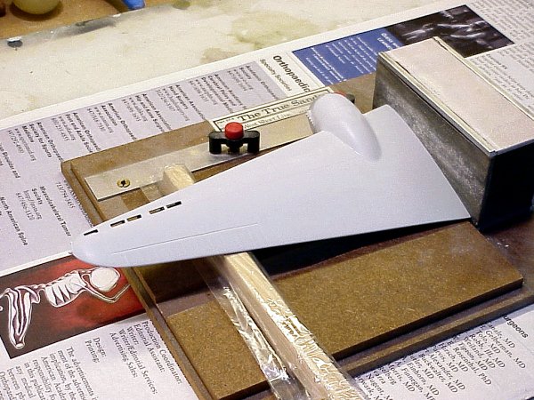
Next I wash the styrene parts to remove any remaining oils or other contaminants that would interfere with modeling paints. Then I shoot all of the mating surfaces of the major kit components (fuselage, wings, tail, nacelles) with Tamiya acrylic Flat Aluminum. I also shoot the areas inside the outboard sections of the wing halves and what will be the inside of the wheel wells Flat Aluminum as well. Note: the slots on the outboard sections of the wings are the predecessors of today's leading edge flaps/slats. At slow speeds/high angles of attack, air is drawn into the scoops on the underside of the wing and is blown out over the top of the wing and over the ailerons providing enhanced roll control at or near stall speed. Since the inside of the kit wing is visible through these slots, the Flat Aluminum is better than bare plastic!
When the aluminum has dried, I removed each part and sand each mating surface on a sheet of sandpaper taped to a sheet of glass. As you sand each joint, any remaining silver highlights a flaw or other problem that would otherwise cause a gap during assembly. When the silver is gone from the edges, you'll have a smooth assembly.
Once all of the major parts have been sanded, I painted the interior of the fuselage and all of the resin parts Model Master RAF Interior Green.
Assembly
First up was the cockpit. I assembled the resin parts per the instructions and painted the details as I went along. The rear cockpit bulkhead (R12) and the lower bulkheads that form the nose access crawlway go together with no problems. The cockpit floor (R1) mounts upon this assembly and overlaps above the floor on R12. Take a good look at the diagrams in step three to see how this works. The forward bulkhead (R11) mounts against the crawlway wall (R3) and cockpit floor. Once you get this structure together, the rest of the details are a snap.
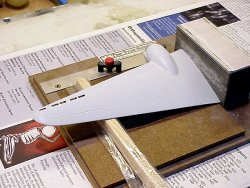
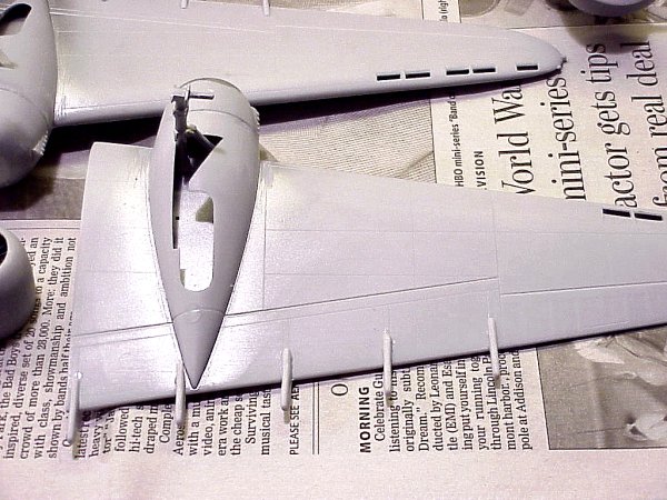
While the interior was drying, I jumped ahead to the wings. I glued the upper/lower wing halves together with Testors Liquid Cement to ensure a solid joint. While one wing matched up perfectly at the wingtip and wing root, the other was slightly off. No problem - I matched up the wingtips, as I'll deal with the wing root later.
One of the critical assembly areas will be the engine nacelles and the nacelle/wing subassemblies. I assembled the nacelles and the engine mount bullet fairings. As these dried, I began to dry-fit the underwing nacelle fairing that also doubles as the main wheel well. Careful sanding and fitting resulted in a good match.
There are three molded-in dents in the underside of the wing where the main landing gear is supposed to attach. There are mounting pins on the main gear struts, but no holes in the wing. No problem - I drilled out the dents and made a few adjustments to get a solid join with the main landing gear struts. Please do this before gluing the underwing nacelle fairing into place, as you won't be able to reach this area easily afterwards.
 Now for the wing roots. I initially didn't sand the wing roots on the fuselage halves, as they looked flat and smooth. You know what they say about assuming. I went back to the sandpaper on the glass and gave the fuselage wing roots a quick rubbing down. Sure enough, there were still shiny spots in the areas where the wing would attach. A little more sanding rendered a smooth flat surface. Next, I set up a square sanding block and a good surface where I could prop the wing up to its proper dihedral angle. I sanded the wing roots on both wings until I achieved good flat joints. Please check your work frequently as you could overdo the process! When I was finished I had a solid wing-fuselage joint that would require little or no filler. I installed the underwing nacelle fairings and set the wings aside to dry.
Back to the fuselage - I finished assembly of the cockpit interior, painted any remaining details that needed attention, and dry-fit the assembly inside the fuselage halves. It is hard to tell how the interior is supposed to sit inside the fuselage, but the rear bulkhead actually goes behind the first side window and the pilot's armor plate/seat mount sits about flush with the rear edge of the cockpit opening. This puts the forward (bombardier compartment) bulkhead about half an inch inside the front of the nose. With the interior in place, the fuselage halves should go together as easy as if the interior wasn't installed. Something was obstructing the fit on my example, so I peeked up the tail toward the cockpit to see where the problem was. In this case, the right side of the aft bulkhead and the instrument panel needed sanding/reshaping and the forward bulkhead was being obstructed by a molded-on ridge in the left fuselage side for the cockpit floor. A little creative sanding and filing rendered a good interior fit.
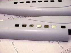 One major compliment to Classic Airframes - this is the first kit that I have ever built where the fuselage side windows - all of them - fit without fuss into the corresponding holes in the fuselage. I was actually dreading this part of the construction, but I was simply amazed at the ease of this step. Note that the thickness of the windows is thinner than the fuselage, so ensure that the windows are flush with the outside of the fuselage before cementing these into place. I used a needle applicator to apply Tenax 7 into the window edges.
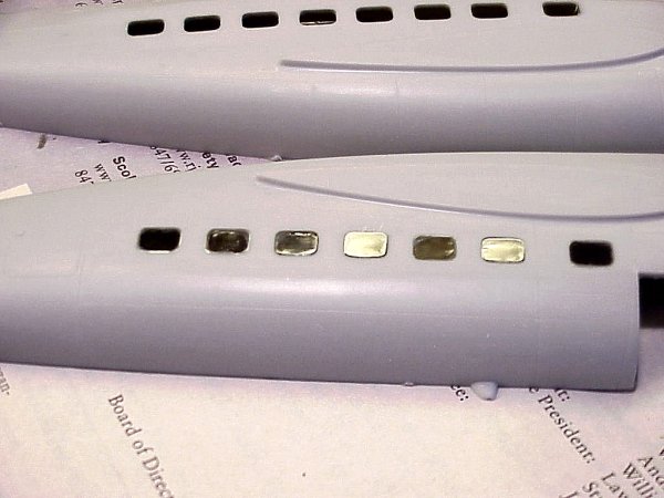
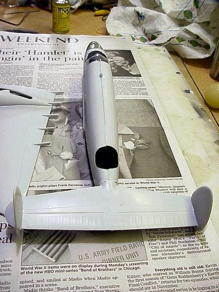
With the windows and interior ready to go, I glued the fuselage halves together. Once again I used Testors Liquid Cement to get the strongest bond. You'll see that once half of the fuselage is slightly longer than the other. I aligned the halves at the cockpit and radio antenna mast. The resulting slight step at the nose was easily sanded into a good surface for the forward nose assembly. The dorsal turret hole will take a little work to compensate but we'll deal with that later.
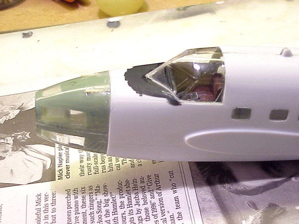
 The bombardier's nose is comprised of three clear parts (top (C4), bottom (C2) and forward blister (C8)) with resin details installed inside. While the simplest approach would be to mask and paint the exterior of C2 & C4 RAF Interior Green and install the details, you'd still likely see the shine from the clear plastic where there should be none. I decided to hand-paint the interior walls RAF Interior Green except for the window frames. This knocks off almost all of the improper "interior reflections" while the window frames will be dealt with from the outside. A work table goes in near the forward top edge of C2 while the bombardier's seat assembly goes in over one of the lower windows.
 Two machine gun barrels are supposed to protrude from the top half (C4). You'll need to drill two holes, then use the drill bit to create a trough for the barrels to lie in. I finished the troughs with a small needle file to get the barrels into proper orientation. Remember to cut the barrels down to the lengths described in the instructions. With the top and bottom halves of the nose ready to go, I used Tenax to assemble them together and to mount this assembly to fuselage.
 The tail section was really simple. With all of the pieces subjected to the sandpaper on glass, the horizontal and vertical stab halves all went together nicely. Each vertical stab has a cut-out that mates to a corresponding cutout on the horizontal stab. The tail literally snaps together. Take care that the cut-outs on each piece are perfectly aligned when gluing the halves together. Once the parts are dry, you'll need to file the openings in each cut-out to get a good fit (they're molded slightly undersized). Dry-fit the parts frequently as not to create too large of a slot. If all goes well (and it is hard not to), the tail section goes together perfectly squared.
The tail section goes onto the fuselage with no problems either. I had used a clamp on the tail to keep the fuselage mounting surface for the tail section aligned while the fuselage halves dried. This worked out great as the tail section mounts to the fuselage perfectly horizontal. Due to the earlier issue with the differing length fuselage halves, there is a small gap on top of the fuselage/tail section joint. This is filled in with small bits of styrene strip and cyano.
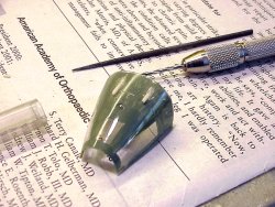
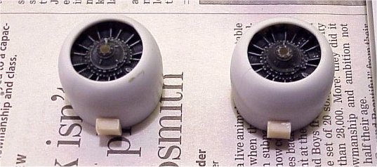
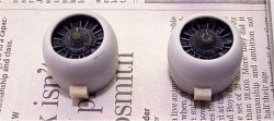 The engine cowlings were assembled next and the resin engines painted and installed. Sandpaper was wrapped around the cowlings and the underside of the resin carburetor intake scoops were then sanded to shape. Once a good fit was achieved, the scoops were cyanoed into place.
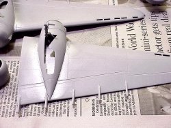 The engine nacelle fairings and engine-mount bullet fairings were installed on the wings with Testors Liquid Cement. The resulting joints, like all of the others, is strong and tolerant of being flexed. I did have to apply a little cyano filler in a few spots, but this blended all of the parts into one good-looking assembly. I took both wing subassemblies along with a sanding stick and buffed all of the seamlines smooth/invisible. I dry-fitted the landing gear struts once again just to ensure that there won't be problems in final assembly.
End of Part One
Well, we're up on the deadline for Internet Modeler, so this ends Part One. We'll mount the wings, assemble the dorsal turret, mask the windows and apply the paint and markings in the next issue.
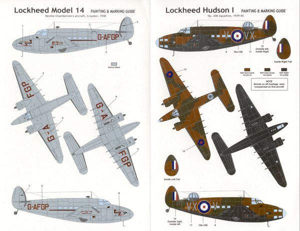
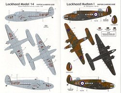 For those of you who are about to get one of these great kits, you'll want to know that the kit provides markings for two aircraft - a Lockheed Model 14 in UK civil registry and used by Neville Chamberlain to try and forge peace with Nazi Germany in 1938, and a Hudson Mk.I of 206 Sqn used in 1939-1940.
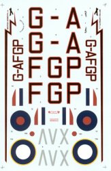 The days of cool decals from aftermarket companies being released before or immediately after a major kit release are over (for now). It is now months (and sometimes years) before decent decal options are available for a new kit subject. Not for Classic Airframes kits - in a new direction for this company, they are releasing additional decal sets (reviewed elsewhere in this issue) to provide the builder with more options when you buy the kit. Another kudo for CA!

See you next month!


![]()


