RPM 1/35 Alkett Minenraumer
|
 |
Introduction
In the February issue of Internet Modeler, I did the in-box
review of this kit. Therefore, I will not repeat the history of
the vehicle.
When I first looked into the box it looked like it was going to be
a good kit and not too difficult to build. Boy, was I ever wrong!! The
first big problem that arose was the fact that there are no part numbers
molded next to the parts on the trees. You have to refer to the parts
tree drawings on the instructions. Here is where the trouble begins.
Throughout the assembly steps the part numbers given are wrong. This
does not clear up and become right until step no.18 of the 30 assembly
steps given.
For those of you who buy this kit here are corrections to the instructions:
STEP #1: The two halves of this small rear wheels are given as one
each of B1 and B2. It should say to use two of B8. You want to line
up the ends of the pins on each side until they all look like one continuous
pin each. I found that the center raised ring inside each half of this
wheel needs sanding down just a bit so that the pins all touch each
other solidly. As molded, these circles sit higher than the surrounding
pins.
 STEP
#2: This is the assembly of the two halves that make up each of the
inner link braces that go around the edge of this rear wheel. They are
given as two of the B3s. It should say 2 of B9s - until you have 10
of them assembled. After you sand the seams, set these aside for right
now. STEP
#2: This is the assembly of the two halves that make up each of the
inner link braces that go around the edge of this rear wheel. They are
given as two of the B3s. It should say 2 of B9s - until you have 10
of them assembled. After you sand the seams, set these aside for right
now.
Step #3: This is the assembly of the inner rings of links that sandwich
the small wheel and the braces. They are given as B4. However, it should
say use B10. Then there are two types of these links - they are different
- but all are labeled as B10 on the parts tree drawings. You want to
use the ones with the solid ends on the raised pins for the inner ring
and not the ones that have the ends of these pins with a hole in them.
The pins should face inward on both sides when linking these together.
Do one ring and lay it without any glue face down, the side with the
pins facing up. Then place the wheel over this and align things so that
it becomes more or less an oval.
You want three of the links to be more or less straight at the bottom
of the wheel. Also, dry fit a couple of the inner brace pieces so that
they engage the holes in the center section well. Then squash the upper
part of the ring of links so that the uppermost links and the braces
will engage things there. Make sure the brace pieces are straight up
and down. When things look good, glue these parts all in place.
Once dry, lift this up, and place the other ring face down on the
table without glue and lay the ring that you have glued into the oval
shape on top of the other ring and push it around until it matches the
first one. Carefully glue it all together when it matches the first
ring. Now start gluing the rest of the braces into the holes with the
other few braces that you did earlier. Now, line up the second ring
and pop the location pins on the braces - make sure they are all straight
up and down and aligned with the edges of the links. Glue the whole
together. This sounds a little involved, but is the best way to assemble
this part.
Step #5: This is adding the outer ring of links to the small rear
wheel. This time you want to use the B10s (not the B4s it says) that
have the holes in the ends of the raised pins. I glued these - raised
pins to the outside - in groups of three. I dry linked three together
and glued the first one in the chain to the raised part of one of the
inner links. Then I would pivot the second link around after putting
glue on the surface of the next inner link - while adding another link
to the third link without glue each time. This was continued all around
the circle until the tenth one was glued in place. You have to do this
to each side and make sure the hollowed out raised pins face outwards.
Step #6: Is the assembly of the two halves of the smaller articulated
FEET that go around the edge of the wheel assemblies. This step calls
out part number B6. It should say B11.
 You
want to place the holes in these over the raised pins with the holes
in the ends of the ring of links. You will find that if you enlarge
the holes a tiny bit you will get a better fit. Also, I found that sanding
the edges of the wheel assemblies helped bring the two halves of these
feet together better. The small retaining straps then go into the rectangular
recesses, molded into the base of each of these feet. These tiny parts
are very hard to handle because of their teeny size, so be careful not
to lose them into your carpet. I lost a few - and thank goodness there
were spares in the kit. You want to make sure that the two raised rivets
on these retaining straps face outward. These tiny parts are called
out as B6 and this is correct for once. Make sure three of these feet
are pretty much flat or lined up in a row with each other. This will
be the ones that touch the ground. The other should be positioned so
that gravity is pulling them down around the rest of the wheel. So pivot
them in the direction of the ground in most cases. They were very heavy
steel units on the actual vehicle. The two halves of these FEET were
a lousy fit around things - so some judicious sanding was in order to
the parts between them to get them to mesh together well. You
want to place the holes in these over the raised pins with the holes
in the ends of the ring of links. You will find that if you enlarge
the holes a tiny bit you will get a better fit. Also, I found that sanding
the edges of the wheel assemblies helped bring the two halves of these
feet together better. The small retaining straps then go into the rectangular
recesses, molded into the base of each of these feet. These tiny parts
are very hard to handle because of their teeny size, so be careful not
to lose them into your carpet. I lost a few - and thank goodness there
were spares in the kit. You want to make sure that the two raised rivets
on these retaining straps face outward. These tiny parts are called
out as B6 and this is correct for once. Make sure three of these feet
are pretty much flat or lined up in a row with each other. This will
be the ones that touch the ground. The other should be positioned so
that gravity is pulling them down around the rest of the wheel. So pivot
them in the direction of the ground in most cases. They were very heavy
steel units on the actual vehicle. The two halves of these FEET were
a lousy fit around things - so some judicious sanding was in order to
the parts between them to get them to mesh together well.
The first Step #7: (For some strange reason there are two step #7s)
is the assembly of the rear wheel bracket and axle pins. If you want
to get at things and paint all of this later, I suggest that you glue
the axle pins so that the wheel will rotate afterwards. You don't want
to glue things all solid here yet as this has to sit flat with the front
wheels when they are done. You will find that RPM did not mold the holes
all the way through the two bracket pieces for the axle pins. I took
a pin vice drill and drilled the holes all the way through from the
rear- testing that the size was now good with one of the pins. Also,
inside each bracket were two raised molding pins, which I sanded off.
The second Step #7: This is the assembly of the two large front wheels.
The step calls out two of part numbers B8. It should say one of part
number B1 and one of B2. Again, line up the pins, on each half, so they
match each other as continuous.
Step #8: Is the assembly of the two halves of the larger inner link
braces. They are called out two of part number B9. You should use part
number B3 and make 20 of them. Ten of which will be used for each front
wheel.
Step #9: Is the assembly of the inner rings of the larger links.
The step says to use parts B10. However, it should be to use parts B4.
Again there are two types of these links on the parts trees, all labeled
as B4 on the parts drawing. You want to use only the ones with the solid
ends to the pins again for the inner rings. The same comments apply
here as the ones I made about doing the small rear wheel ones. Sandwich
your brackets between the two link rings the same way.
 Step
#10: Is the assembly of the inner rings and brackets around the large
wheels. Make sure you do the oval pattern again - with three links pretty
much in a row again. Read earlier comments again about how I did this
on the small rear wheel. RPM uses a shaded number in an assembly to
show an earlier assembly being used. In this step they have the assembly
numbers 1 printed. It should show the shaded assembly number as being
7 and 9. Step
#10: Is the assembly of the inner rings and brackets around the large
wheels. Make sure you do the oval pattern again - with three links pretty
much in a row again. Read earlier comments again about how I did this
on the small rear wheel. RPM uses a shaded number in an assembly to
show an earlier assembly being used. In this step they have the assembly
numbers 1 printed. It should show the shaded assembly number as being
7 and 9.
Step #11: Is the assembly of the outer rings of links. Do these using
the same method as on the small wheel assembly earlier. The links are
called out as B10. It should say B4. Use the ones with the hollowed
out ends on the raised pins and make sure these point outwards again
on each side. Make two of these wheels now.
Step #12: This is the assembly of the large articulated feet. The
same comments apply to their assembly as did for the smaller ones on
the rear wheel. The instructions say to use parts B11. It should say
use parts B5. You also add the little retaining straps into the rectangular
recesses. Make sure that the two raised rivets face you. These are called
out as B6 again, like the ones on the small wheel's feet, it is correct.
Step #13: This is the assembly of two small pieces that make up the
V shaped foot steps that go just behind the tow rings on each side of
the vehicle's glacis plate. I found that two of these had sink marks
in the back of them. Also, one piece would have rounded corners and
the next one square ones. I decided not to use these. I glued two of
the pieces together, to get the size of the completed unit. I measured
this and made two duplicates of these from scrap PE brass. The kit ones
are also too thick looking, to my eye. The brass ones will look more
correct. I bent these pieces into a V using my Small Shop brand PE bending
jig.
Step #14: Is assembly of the chassis lifting hooks. These are super-small.
I cut the hooks off the trees while my hands were inside a cello bag.
This prevented these little devils from flying off into oblivion. You
only need eight of these: four on each side of the upper edge of the
hull roof. The hooks should point downward after gluing them in place.
I glued the hooks to the base plates while the plates were still attached
to the sprue. This made it easier to do. The part numbers are called
out correctly.
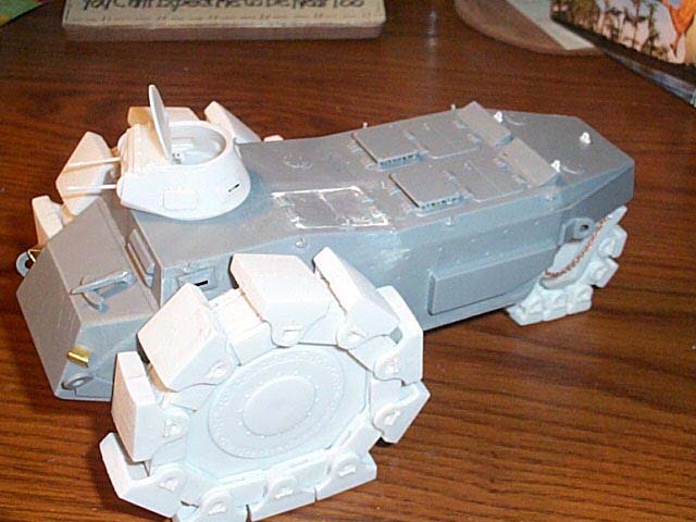
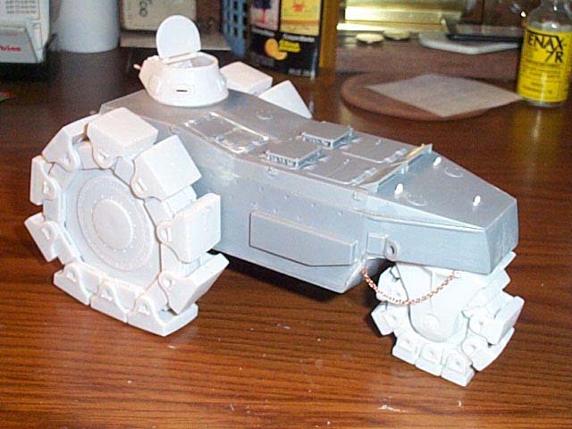
 Step
#15: Is the assembly of the vehicles hull. All parts are numbered correctly
here. However, the two sidepieces in my kit were rather warped. I held
them next to a hot light bulb - but that did not work. I then held them
under scalding hot water from the faucet. This did straighten them somewhat.
The final thing, to get them straight, was to glue them to the other
hull pieces an inch at a time - straightening them as I went. Make sure
the first inch is dry before doing another inch. This worked well. Step
#15: Is the assembly of the vehicles hull. All parts are numbered correctly
here. However, the two sidepieces in my kit were rather warped. I held
them next to a hot light bulb - but that did not work. I then held them
under scalding hot water from the faucet. This did straighten them somewhat.
The final thing, to get them straight, was to glue them to the other
hull pieces an inch at a time - straightening them as I went. Make sure
the first inch is dry before doing another inch. This worked well.
Step #16: Is adding a vision slit part to the driver's side of the
hull, access doors to the roof, and air intake vent slats. The access
doors had rounded corners near the hinges and the opening they went
into has square corners. I glued them closed and then the next day I
used Miliputt putty in the gaps at the corners. In hindsight, I should
have cut the hinges from the door pieces and made new doors from sheet
plastic adding the hinges back to them. The vent slat pieces should
be glued in the openings at an angle - slanted towards the front of
the vehicle. Careful with these as they may fall inside the hull on
you. All part numbers shown in this step are correct again.
Step #17 Is gluing the covers that go over the vent slats, adding
the hull lifting hooks, the PE footsteps I made, and the front and rear
tow ring parts. All part numbers are correct.
Step #18 is the assembly of the two machine guns for the turret.
All part numbers again are correct. I painted these guns with Model
Master gunmetal enamel.
Step #19 is assembly of the turret gunner's seat. I painted the cushion
khaki with Poly-S acrylic and left the support rail bare - as it is
already molded in white plastic - so needs no other painting.
Step #20 is the assembly of what I think is a tray to hold ammo??
There is an off-set hole in the bottom of this and the instructions
do not say which direction it should go. I just winged it.
Step #21 is assembly of the the lift hooks that go on the turret
roof. There are three of these little devils and - again - I glued the
hooks to the bases while they were still on the sprue.
Step #22 is the assembly of the machine guns into the inside mantle
piece.
Step #23 has us install the inside mantle piece into the outer one,
along with the two machine guns, some sort of a framework between them,
and two inside mantle retainer yokes..
Step #24 has us assemble the bottom and two side pieces of the turret.
Step #25 shows us to assemble the roof of the turret.
Step #26 is the assembly of the gunner's seat and ammo tray into
the turret.
Step #27 shows us to assemble the mantle assembly into the front
of the turret.
Step #28 is the assembly of the three lift hooks to the roof of the
turret, adding the vision slits and flaps to it, and the hatch lid.
Step #29 is the assembly of the plastic chain in the kit. I did not
use this - as I found these to be virtually USELESS. They are attached
to the trees with the attachment points coming well out onto the links.
If you do get them off the trees in decent condition, then they are
too bulky and dont want to fit into each other without binding and
you wind up with a straight chain. I gave up in disgust and canabalized
some of the chain out of my Tamiya M26. It appears there is enough extra
in that kit to spare for the Minenraumer. I hope I am right in this.
I will find out for sure - later - when I build the M26.
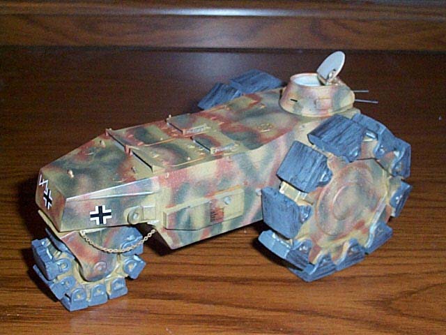
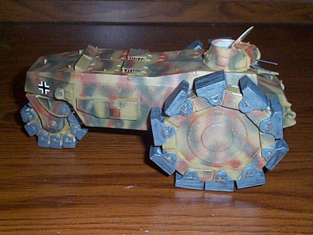
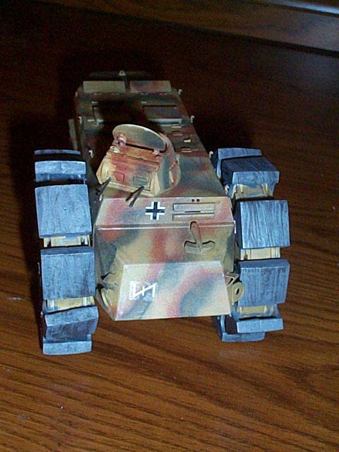
 Step
#30 is where the sub-assemblies all come together into a whole. I painted
the turret, hull, and the two large wheels off the model. The base coat
is Model Master dunklegelb acrylic oversprayed with lines of Poly-S
armor red-brown acrylic. The feet on the wheels were painted a dark
iron color and dry brushed with Model Master enamel stainless steel
buffing formula paint. Hatch edges and around other fittings were picked
out with a wash of burnt umber oil paint. The decals are from Archer
dry transfer - for the national crosses. I only used the load weight
stencil off the kit decals on each side and Hitlerjugend Division marking
front and rear. I chose this division, because the box art calles out
Kursk and this division was at that battle. These marks came off an
old Super Scale sheet. I then shot the decals with a light coat of Testor's
spray dull-coat. Step
#30 is where the sub-assemblies all come together into a whole. I painted
the turret, hull, and the two large wheels off the model. The base coat
is Model Master dunklegelb acrylic oversprayed with lines of Poly-S
armor red-brown acrylic. The feet on the wheels were painted a dark
iron color and dry brushed with Model Master enamel stainless steel
buffing formula paint. Hatch edges and around other fittings were picked
out with a wash of burnt umber oil paint. The decals are from Archer
dry transfer - for the national crosses. I only used the load weight
stencil off the kit decals on each side and Hitlerjugend Division marking
front and rear. I chose this division, because the box art calles out
Kursk and this division was at that battle. These marks came off an
old Super Scale sheet. I then shot the decals with a light coat of Testor's
spray dull-coat.
Conclusion
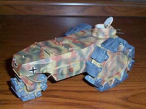
This is surely an unusual, and salty-looking, vehicle. Bound to draw
stares on any model's model shelf. I intend to take mine to a few contests
and see how it fares.
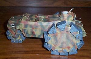
Except for some errors on the instructions and the lousy chains in
the kit. I enjoyed building this model. I left the hatch lid open to
maybe add a figure there later. It sure was nice that RPM molded the
turret in white plastic - no need to paint the interior then.
| 


|