Building the Khee Kha 1:72 Bellanca CH-300 Pacemaker
|
 |
Introduction
An ‘in-the-box review’of Khee Kha’s Bellanca CH-300
Pacemaker, including a short history of the type, was published on IM
by Jim Schubert in January 2006.
The CH-300 Pacemaker is the ‘sister’ kit to the CH-400 Skyrocket
(also the subject of an ‘in the box review’ by Jim Schubert
in Oct 2004 IM), and the third in Lars Opland’s Khee Kha vac-form
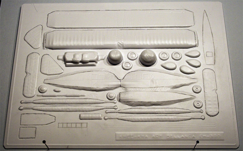
series. The Pacemaker kit contents and documentation follow the same format
as that of the Skyrocket, a single vacform sheet for the essential airframe
components and a set of resin pieces for the prop, engine, cowling and
exhaust manifold. No decals are provided.
Choice of Aircraft
 I
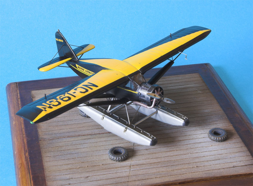
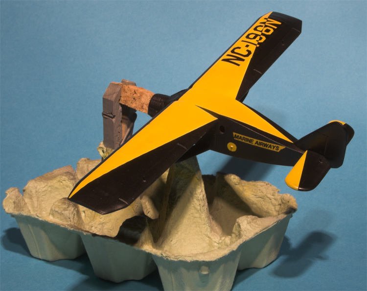
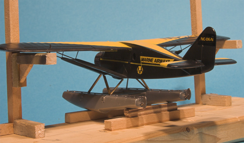
made a decision at the outset to model ‘Shakey Jake’, a float
equipped Pacemaker (NC-196N) belonging to Marine Airways of Juneau, Alaska.
First introduced to this particular aircraft in the pages of Jim Ruotsala’s
book Alaskan Wings, I was particularly pleased to see that Lars had included
very useful three view drawings of ‘Shakey Jake’ in the building
instructions included with the kit. I
made a decision at the outset to model ‘Shakey Jake’, a float
equipped Pacemaker (NC-196N) belonging to Marine Airways of Juneau, Alaska.
First introduced to this particular aircraft in the pages of Jim Ruotsala’s
book Alaskan Wings, I was particularly pleased to see that Lars had included
very useful three view drawings of ‘Shakey Jake’ in the building
instructions included with the kit.
The striking black and yellow colour scheme promised to provide a quite
different looking model. Creating the EDO K-4650 floats that Pacemakers
were generally equipped with was obviously going to be a challenge but
challenges are what enjoyable modelling is all about. (See final section
for details of a resin set of floats now available)
Preparation of the airframe components
Included with the kit is a detailed set of building instructions which
provides plenty of helpful hints for those modellers unaccustomed to vacform
building. However experienced a modeller you might consider yourself it
is well worth sitting down and reading through these in detail a couple
of times in order to formulate a sensible build sequence for your particular
airframe, especially if it involves a variant with skis or floats.
 |
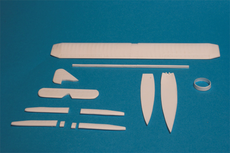
Removal of the components from the backing sheet followed conventional
vacform practice - outlining the individual parts with a heavy pencil,
scoring at 45o with a sharp knife and then ‘snapping’ out
the pieces. The thickness of the plastic became evident at this point
and some additional scoring was required to extract some of the pieces.
The exact contours of the fuselage nose/windscreen region were a little
difficult to determine on the backing sheet so I left a generous amount
of ‘waste’ in this area until the precise profile could be
verified. This is important because of the need to ensure a snug fit with
the resin cowling piece later on in the build.
The Townend ring was cut out using the method detailed in step 14 of
the instructions. The ‘shipping cup’ used to pack the resin
engine is cut out from the backing sheet and rotated carefully on a flat
surface against the point of a sharp knife blade. The blade is held parallel
to the surface at the required height by taping it to scrap sheet laminations.
This resulted in nice clean extraction of the ring from the shipping cup,
an exercise which could have been very tricky if attempted using a razor
saw.
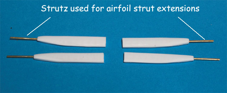
I removed the extensions to the airfoil wings struts as I felt these
were overscale and would be better represented with ‘Strutz’
replacements later on during construction.
The undercarriage legs and wheels were left intact on the backing sheet
and consigned to the spares box as they were not required for Shakey Jake.
Wings
Although the instructions cover fuselage assembly next I decided to
work on the mainplane as the first area of construction. Not having built
a vacform for many years I felt it would be beneficial to ‘sharpen
up’ old skills on the wings first before addressing the complex ‘joinery’of
the curvaceous fuselage.
The upper and lower wing surfaces are removed from the backing sheet
as one piece full span components. Separation into port and starboard
wings only occurs after the upper and lower surfaces have been prepared
and joined.
Both upper and lower surfaces were sanded to produce acceptably thin
trailing edges. This was a demanding task due to the thickness of the
backing sheet but the advantage of the inherent component strength outweighed
the downside of a lengthy filing and sanding exercise. I retrieved my
old Aeroclub aluminium ‘T bar’ and sticky pad tool set from
the depths of the tool box and it proved ideal for gripping the wing components
during sanding operations.
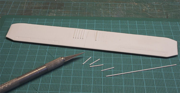
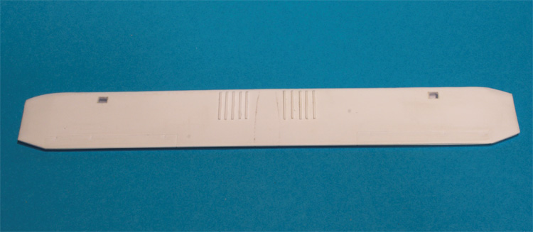
After joining the upper and lower surfaces thin plastic strips were
added to the mainplane underside to represent the prominent strakes of
the full size machine. The mouldings have clear indications of the length
and lateral separation of these features so it was a simple job to add
the strip over the top of each one. Once the glue had cured they were
sanded to the correct profile and cut-outs made for the aileron control
cable inspection clear panels.
The completed mainplane was then set aside pending its separation into
two wing halves following completion of the fuselage assembly.
Fuselage
I found a very useful photo on the Khee Kha website which showed the
cut out Pacemaker fuselage sides in close up. This resolved the question
as to the exact shape of the fuselage cowling area ahead of the windscreen
which needed to be ‘notched’ to accept the resin forward cowling
piece correctly. A small sketch diagram in the instructions would have
been useful to clarify the ‘relationship’ between these two
components.
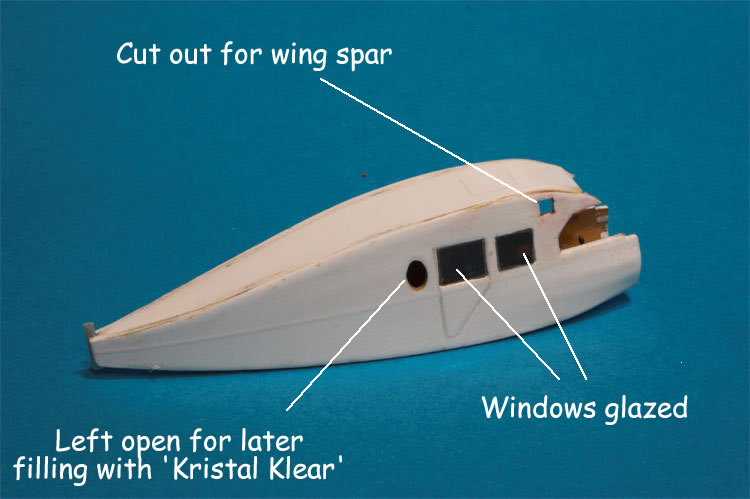
Closely following steps 3-6 of the instructions, the window and main
spar cut outs were made and joint re-enforcing strips added to each fuselage
side. These strips would allow the fuselage top and bottom pieces to line
up nicely with the contours of the fuselage side profile when making the
joint. Following the recommendation in the instructions approximately
2mm long strips were glued at regular intervals along the fuselage profile.
This made for easier following of the fuselage curvature than would a
single continuous piece of plastic. A test fitting of the top, bottom
and side components using several strong rubber bands showed that only
minimal filler was going to be required following final gluing.
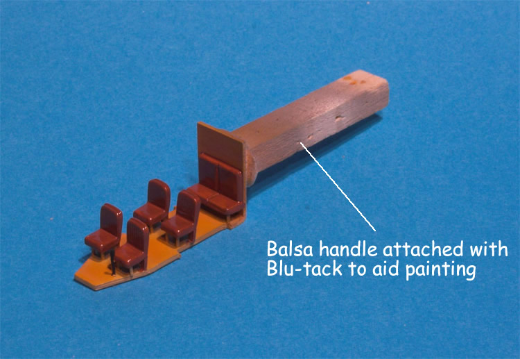
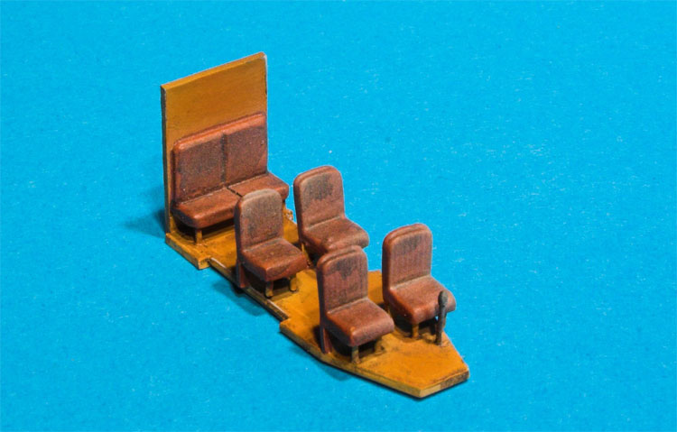
Attention now focused on the fuselage interior. I elected to use some
spare seats liberated from the MPM Lockheed Vega kit for four of the seats.
The bench seat attached to the rear bulkhead was fabricated from the vacform
parts.
The interior was painted and ‘weathered’ with Humbrol enamels
to give a general impression of a well worn working aircraft.
Once the interior was thoroughly dry all the fuselage components were
brought together and carefully joined using liquid cement. The accuracy
of the vacform parts and the use of reinforcing strips combined to make
this a straightforward exercise. Plenty of Tamiya tape was used to keep
the parts together until the cement took real hold.
The resulting assembly was carefully checked for symmetry and then any
minor gaps filled with Squadron Green Stuff.
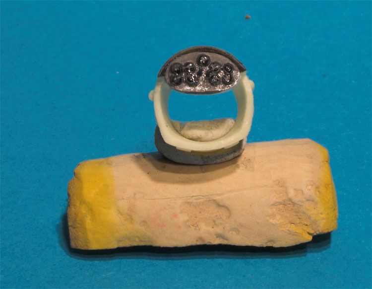
Using the vacform template provided, and with reference to various pictures
of Pacemaker instrument panels, a simple representation was fabricated
and attached to the resin cowling. Visibility of the panel was going to
be limited in the finished model so detailing was kept to a minimum.
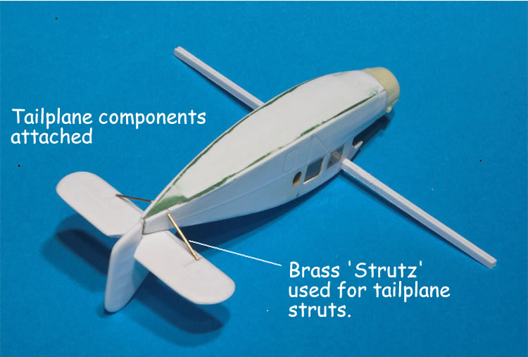
The rudder and elevator trailing edges were given a vigorous sanding
and all the tailplane components were attached to the fuselage. I was
not able to achieve quite the scale thickness of the tailplane leading
and trailing edges that I would have liked but this was due to my inadequate
filing and sanding rather than any inherent fault in the mouldings. The
tailplane struts were added using brass Strutz to give real strength in
this area.
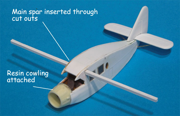
The wing spar was carefully threaded through the fuselage cut outs and
fixed in place with a touch of liquid cement. Once in place the laminated
spar formed an extremely strong basis for wing attachment – a very
nice design element in the kit.
To complete the basic fuselage assembly the resin cowling, together
with the attached instrument panel, was fixed in place. Some minimal sanding
of the fuselage sides was required in order to remove a slight ‘lip’
between the plastic and the resin. Lars makes the point in his instructions
that this ‘metal cowl to fabric’ boundary on the full size
machine is fairly abrupt anyway so I did not attempt to create an invisible
joint line. Careful ‘dry fitting’ of the fuselage sides, the
fuselage bottom and the resin cowling at an early stage will pay dividends
in the accuracy of this critical joint.
At this stage I had run out of excuses not to fit the wings. The panels
were thus separated and the wing root profiles gradually refined with
alternate carving, sanding and repeated dry fitting in order to create
a snug fit with the fuselage side. Do not do this late at night when eyes
and hands are tired – save it for an early morning session!
As the wings will rotate slightly around the axis of the spar, care
is needed to make sure that the port and starboard wings exhibit the same
degree of incidence before final gluing occurs. Use a slow setting cement
for the wings so that there is plenty of time to check dihedral, incidence
and alignment fore and aft. Once happy with both joints I put the whole
airframe aside for a week or so to allow the cement to cure completely
before progressing further.
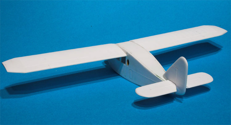
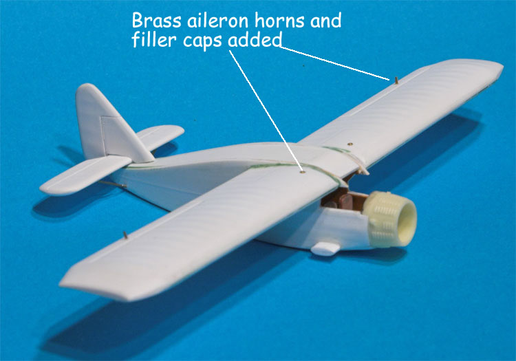
Aileron horns and tank filler caps were added using spare pieces of
Strutz and etched brass. At this juncture I decided to add the horizontal
elements of the airfoil struts to the fuselage as this would give me a
reference point from which to establish the position of the floats and
float strut attachment points.
Although a perfectly acceptable vacform windscreen is included in the
kit I decided to represent the ‘angular’ look of the full
size windscreen with separately fixed flat panels. The windscreen framing
was created using small pieces of guitar string fixed in place with super
glue. Individual clear plastic panels were cut out using the 3 view drawings
in the instructions as a guide. The cockpit coaming was painted a metallic
grey and then each windscreen panel was carefully glued in place using
slow setting CA. This proved to be a tortuous process, but one that I
had inflicted on myself so no excuses! Ultimately I was pleased with the
resulting effect but would recommend that the kit supplied windscreen
is utilised if you are more adept than me at painting (or decaling) cockpit
framing.
The Floats
I took a break from work on the airframe at this stage in order to concentrate
on building the EDO K-4650 floats that Shakey Jake sported. I became aware
during the building of this model that Jim Schubert and Lars Opland were
planning to produce a resin set of 1:72 EDO J-5300s which could be used
in place of the inaccurate examples provided with the MPM Lockheed Vega
floatplane kit. The J-5300s have the advantage of only requiring a simple
modification to produce the K-4650s. I thus had the option of waiting
for this resin set or pushing ahead with a scratch-built set of K-4650’s.
Perverse logic dictated that I would go for the scratch-built option.
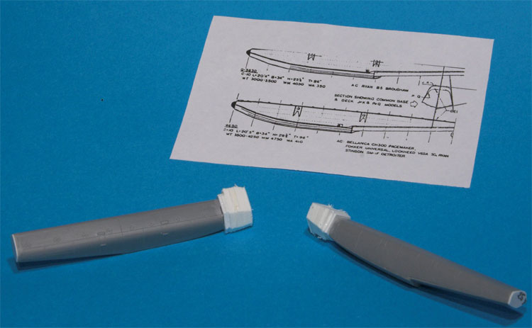
Lars had already kindly provided a set of EDO float profiles and some
very useful photos of a full size set of J-5300s under restoration at
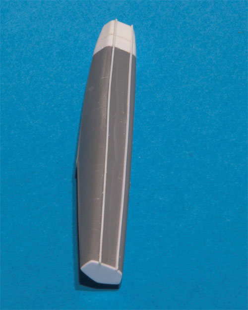
the AAHM (Alaska Aviation Heritage Museum). I made an early decision to
utilise the MPM Vega floats as the basis for my K-4650s as this would
ultimately require less work than starting completely from scratch. Two
major pieces of surgery were required to modify the MPM examples - reducing
the overall scale length and re-modelling the whole nose profile which
in the MPM mouldings has a strange asymmetry not present in the full size
floats. In addition the under surface required additional ‘flutes’.
The paper profile of the K-4650s was scanned and manipulated in Photoshop
to produce an exact 1:72 scale length before printing out several copies.
The correct scale length of the K-4650s behind the step was measured
and the MPM moulding ‘amputated’ accordingly. The whole of
the badly shaped nose piece was removed and laminations of scrap plastic
glued in place to create an overall correct length measured against the
profile.
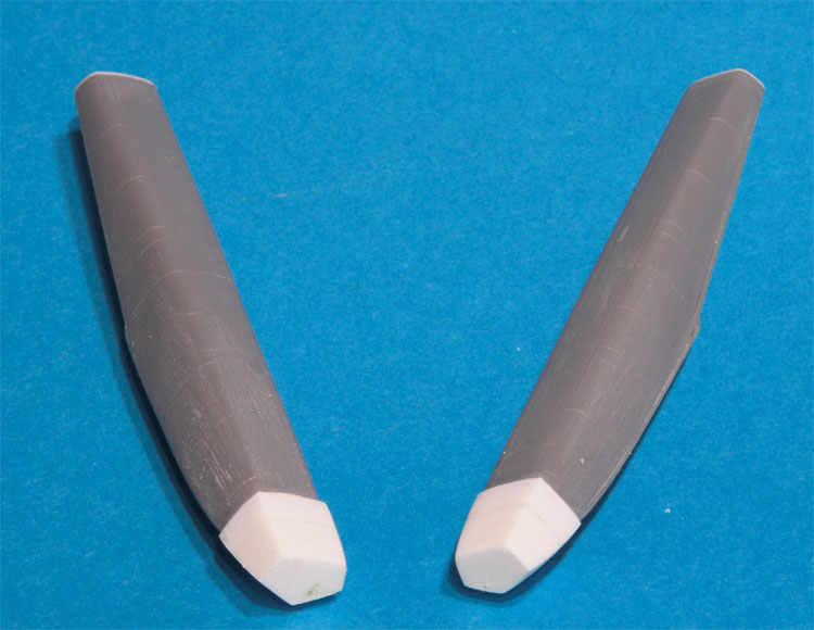
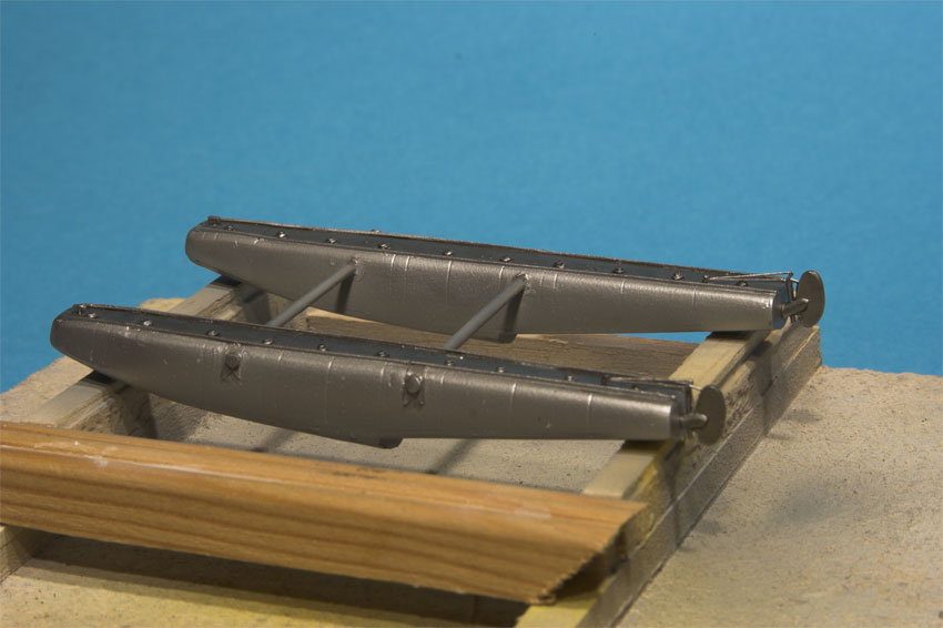
The correct nose profile for the 4650s was produced with careful carving
and sanding of the plastic laminations. The correct ‘fluting profile’
was created using heavily scored thin plastic sheet which was glued to
the under surface of the float. Additional detail was added to the float
top and sides using reference photographs of float equipped Pacemakers
from Alaskan Wings and the Canada Aviation Museum Image Bank.
Spreader bars were fabricated from plastic rod and inserted into holes
drilled into the inner sides of each float. The float spacing was checked
against the 3 view drawings of Shakey Jake in the instructions and the
whole assembly glued together. Water rudders and associated linkages were
added from plastic sheet and stretched sprue. The whole unit was sprayed
with Halford’s acrylic primer before being finished in Alclad aluminium
and weathered with artists’ oils.
At this point I constructed a basic jig from balsa and scrap wood to
hold the separate fuselage and float assemblies in perfect alignment whilst
the float struts were measured up and fitted. The strut attachment points
were determined using a combination of reference photographs and measurements
from the 3 view drawing of Shakey Jake and holes drilled in the appropriate
positions in both the fuselage and floats. First, however, the airframe
required painting and finishing before the floats could be fitted to avoid
difficulties with access to the underside.
Painting and finishing
Before priming the airframe the remaining sections of the airfoil struts
were fitted. Brass Strutz was used for the strut extensions that attach
to the under wing surface.
After a thorough clean up of the airframe it was sprayed with a coat
of Halfords Acrylic White auto primer. White was used in place of the
usual grey primer as the next coat was to be an overall yellow. Two coats
of Aircraft Colors ‘US Orange Yellow’ acrylic were airbrushed
over the entire airframe followed by a careful application of Tamiya tape
in order to create the mask for the attractive diagonal black and yellow
colour scheme carried by Shakey Jake. Two blocks of yellow were retained
in the area where the ‘two tone’ registration number decals
would be placed to avoid any ‘bleed through’ of the underlying
black into the yellow segments of the lettering. Two coats of Aircraft
Colors ‘RLM 22 Black’ acrylic followed to complete the airframe
paintwork.
 |
At the time of building no commercial decals were available for this
particular aircraft so I created my own set using Microsoft Visio and
printed them on Experts Choice clear decal film using an HP inkjet printer.
Although this was a lengthy process because of the complexities of the
black-yellow lettering the end result was very pleasing.
As is always the case in these instances just as I finished creating
my own Shakey Jake decal set I had a mail from Lars announcing the fact
that he was collaborating with Whiskey Jack Productions to produce a set
of attractive decal sheets for the Khee Kha Pacemaker kit, including a
sheet for ‘Jake’. (See end of article)
Once all the decals had been applied the whole model was given two coats
of acrylic varnish to seal everything down.
Attaching the floats
With the paintwork complete it was time to attach the floats. The previously
constructed jig held the airframe and floats securely whilst dividers
were used to measure up the strut lengths. The float struts were fabricated
from brass tube that was gently flattened using a pair of pliers to create
the streamline shape. Before flattening a piece of piano wire was threaded
through the tube to create fixing pins at each end. This was held rigid
by the compression process.
Each strut was inserted in turn into the pre-drilled holes and fixed
with a drop of CA. The resulting structure proved to be very strong. The
struts were painted aluminium and then ‘rigged’ using guitar
string.
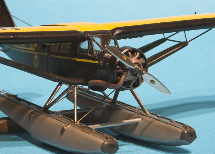
Final Details
All that remained now was to paint the resin engine and prop, fit the
speed ring and manifold, and attach the finished assembly to the nose
section of the aircraft. The basic manifold is provided in the kit, the
modeller is required to add exhaust extensions according to the individual
airframe being modelled. Exhaust configurations varied considerably between
aircraft and careful checking of reference material is required. I made
Jake’s extension using soft aluminium tube that fitted over the
resin piece nicely and could be easily bent to produce the downward curving
configuration depicted in pictures of the aircraft whilst serving with
Marine Airways.
The airframe was completed with the addition of tailplane bracing, a
pitot tube, navigation lights, and aileron control horn cabling.
Conclusions
Khee Kha’s Pacemaker is definitely not a kit for the beginner,
but any modeller who has some vacform experience will find it very manageable.
This is a kit for modellers who favour the ‘engineering’ rather
than the ‘assembly’ approach to kit building. I found the
experience immensely rewarding as it not only revitalised long lost modelling
skills but enabled to me learn much about Alaskan aviation during the
course of researching the aircraft. I am very grateful to Lars Opland
who furnished me with many photographs of the full size machine. Now that
both resin floats and decals are available for the Pacemaker there is
no excuse to not to have a go at building this model.
Khee Kha are to be congratulated for producing such an interesting subject
and I look forward to building their Fairchild F-71 which is already in
my kit stash. At a purchase price of just $20 plus postage the Khee Kha
Bellanca CH-300 Pacemaker represents exceptional value for money.
Details and ordering instructions for Whiskey Jack decals can be obtained
by emailing:gorlem@shaw.ca
References and Bibliography
-
Ruotsala, J., (2002) Alaskan Wings, Aviation in Southeast Alaska
1935-1946 Juneau: Seadrome Press
-
Szurovy, G., (2004) Bushplanes St Paul:Zenith Press
-
|
|