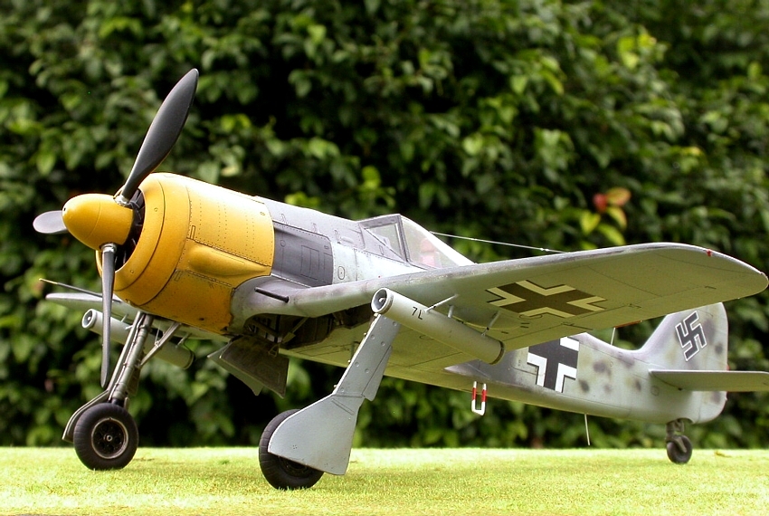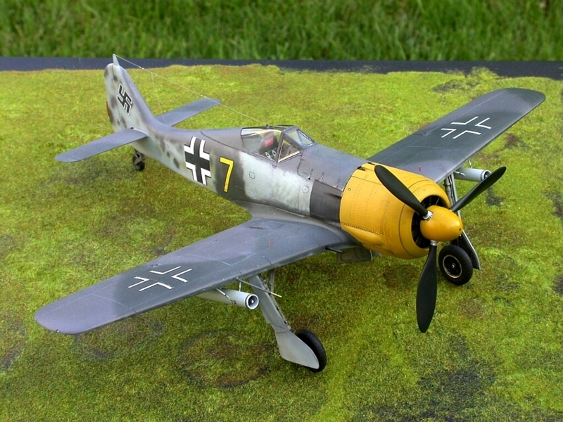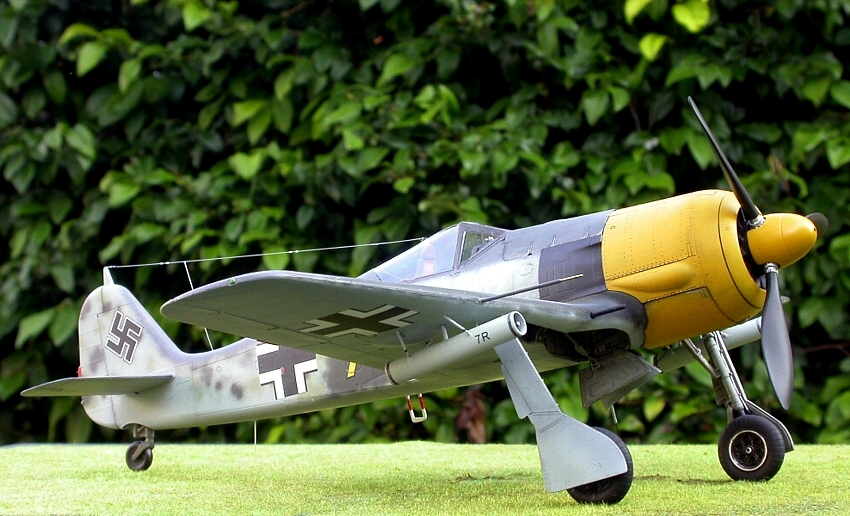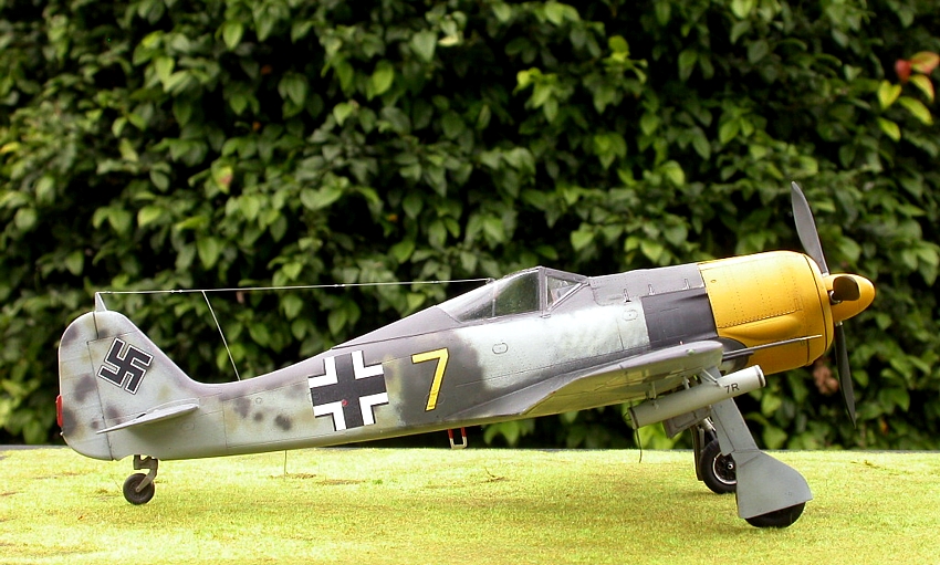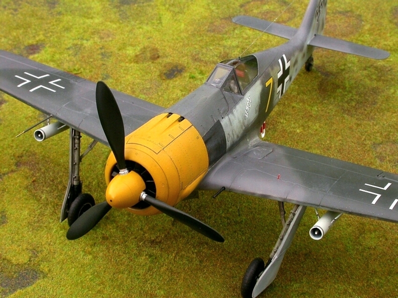
Eduard 1/48 Fw190A-5
By Robert Rensch
Decisions
The Eduard kit provides decals for four aircraft. Three are modeled with the wing MGFF's deleted. In order to correctly model the outer wing gun delete, the hinged access panel under the gun position would need to be modified to a flat panel with a smaller bulge than that for the MGFF ammo drum. I was too lazy to do that, so that ruled out Nowotny's and Strohall's planes.
Since I am particularly interested in JG1, I decided on the WGr.21 equipped plane marked “Uschi”. This is an interesting plane in many ways. First, there are pictures of rocket-carrying 190's with the outer guns deleted that retain the original MGFF ammo drum clearance bulge. Less work for me! Second, I have been able to track down exactly two pictures of this aircraft. They are very similar to one another, and show a ground crewman standing behind the wing near the “Uschi” inscription. Not much to go on, but better than some modeling subjects are documented with.
There is some debate as to the cowl color and the color of the number and inscription. Eduard happily provides both yellow and white numbers and names for the plane. We get to play junior historian and decide which suits our interpretation best.
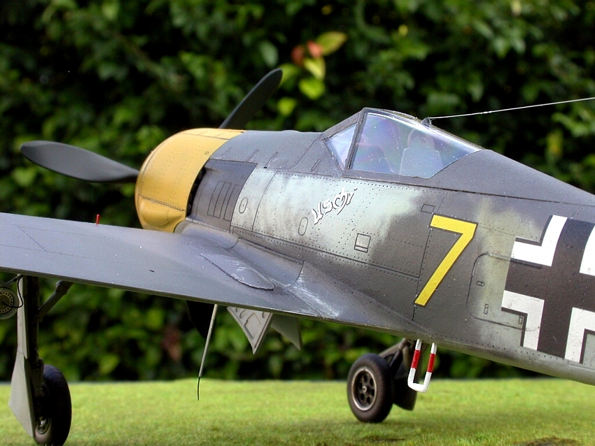
The yellow cowl color is certainly a guess, but it makes some sense. In the summer of 1943, during July most certainly, an Eprobungskommando was attached to the 3rd Staffel for the purpose of testing the WGr21 rocket installation and tactics in combat. I have found four pictures of rocket equipped Fw190s from that time period. They all appear to have light colored, unmarked cowlings. The two pictures that show more than just the cowl and leading edge of the wing (“Uschi” is one, the other is “Yellow 8 used-to-be 9”) appear to be planes that had been used previously, not new planes, and have had greater or lesser repainting/remarking. “Uschi” seems to have had a significant repaint, covering something, perhaps an Adlerflugel (Eagles Wing) painted behind the exhaust outlet, with first possibly RLM 74 gray-green, and then tight up-and-down strokes of RLM 76 blue. The aircraft number was completely overpainted (I decided with RLM 74 and 75 gray-violet), and a new number painted on. I decided that, since the pilot was assigned to 3rd Staffel at the time, and the unit was attached to the 3rd Staffel, that the number was yellow. Eduard's yellow number is slightly paler that the paints I use for RLM 04 yellow, and shows up much like the real variation in grayscale value between the cowl and the number when a picture of the model is converted to grayscale. Okay… Straight RLM 04 yellow cowling it is.
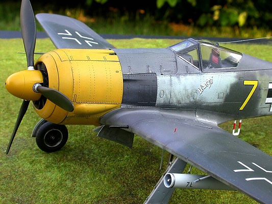
If I was operating a weapon system as different and pyrotechnic as the WGr21 within a group of aircraft not overly familiar with the habits of the rockets, I would want the planes carrying the rockets to be easily identified, especially from the front. “Stay out of the way!” High visibility yellow cowlings and spinners would be a nearly unmistakable identification marking.
The name “Uschi” displays very little contrast with the RLM 76 blue behind it, and allowing for funky contrast in the photo, I decided white would show up less against the blue than yellow would. Okay, yellow number, white name. (I'm betting that “Yellow 8 used-to-be 9” has a name painted on it as well, unseen on the unphotographed side of the plane… Some other photos of 3rd Staffel JG1 planes display names in the same lettering style into early 1944.)
Since “Yellow 8 used-to-be 9” was certainly operating with “Yellow 7, Uschi”, I used the camouflage pattern from it to base my model's paint job on.
I may be right, and I may be wrong, but it all makes sense to me, and I have a ball doing this junior historian stuff. I just wanted to give you my thoughts. You may proceed with your best analysis, and have as much fun with it as you can!
Map through a Minefield
With this kit, Eduard has displayed a great deal of ambition. The basic engine, open gun positions, detailed cockpit and landing gear bay, and the nicely engraved rivet patterns are indications that Eduard was challenging for the best available 48th scale Fw190 kits. Aside from the overly thick vertical fin leading edge, the strangely shaped propeller, and a few minor odds and ends, this kit still has fine potential.
All you need to do to have a respectable replica of the real plane is stay one step ahead of what turns out to be a very tricky build. I have read accounts of these kits ultimately being disposed of partway through the construction process. Some on-line and magazine reviews tell of having to leave out parts, modify others, and really struggle to get a finished product; especially if the builder wants the model “closed-up”.
Well, really, nothing too drastic needs be done. I left the wing gun bays empty, and cut the tops off the cowl gun ammo chutes, as well as leaving out all of the cowl guns save the ends of the barrels. The whole engine exhausts, engine mounts, and miscellany are still there, closed up inside my model and everything lines up. It's absolutely possible. Let me give you a map through a minefield…
Construction
I'm not going to spend much time covering the areas that fit well or cause no trouble. I will go into more detail in the areas that require particular attention. Note; I used only a small spot of putty to fill the flare port on the stbd. side of the fuselage, and a few applications of white glue to fill gaps around the wing gun bay covers and a couple other minor places. Other than that, I used no filler on this kit.
If you are used to only using a “flash” cement like Ambroid Pro-Weld or MEK, I recommend you get a slower setting glue so you can work with things as they set. Being able to do things between glue application and glue “set” is almost mandatory with this model kit. That said, let's begin…
I jumped on the engine assembly first. I found out it is not too complete or accurate, although it is a good basis for adding Eduard's photo-etch detail set. Curiously, the trunks that lead from the supercharger to the intake area on the cylinders are not included either in the kit or in the detail set, but they are illustrated in the instruction sheet.
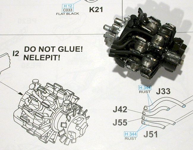
I found it a good thing to leave the cooling fan unglued. Things worked out well enough that I have a positionable propeller now. If you have to take some length off the engine assembly later, as I did, to get the fan and prop in a correct relationship to the front cowl edge, some material can be removed from the back of the fan and the front of the crankcase. I also ended up removing some material from the back plate locating points on the engine-to-engine mount yoke junction. It's good to leave as many options as you can think of as you plan ahead for contingencies.
Then, the cockpit. There isn't much trouble to be found assembling this. I used Elmer's Tacky Glue to attach the photo-etch bits. It provides immediate “stick”, but can be adjusted for a while. There's not much to attach the etch rudder pedals to, so I used blobs of tacky glue on their locations and just stuck them in that.
After you get the cockpit put together, the wing is next. The instructions show the fuselage, but trust me… you need the completed wing to enable you to adjust things in the fuselage for best fit.
Before you do anything else, remove the lower wing section from the sprue and look at it carefully. The nose bottom is not supported by runners from the sprue, and mine was twisted to one side relative to the rest of the wing bottom panel.
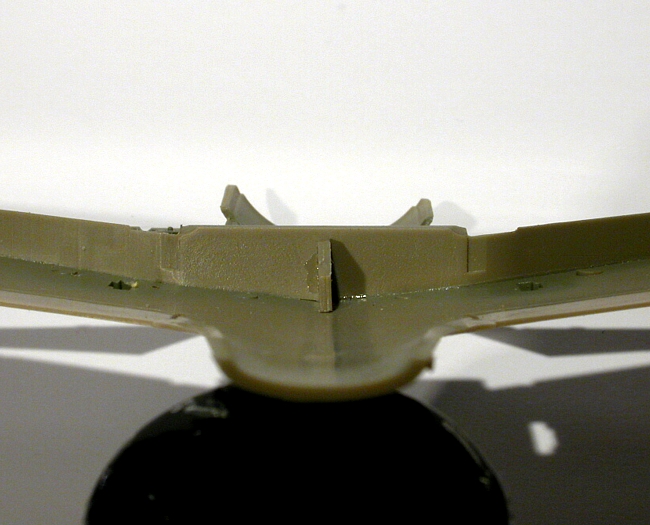
Once you have ensured the cowl bottom and the rest of the wing bottom all align with each other, you get to locate the wing spar. I followed Eduard's instructions to the letter… and later found out there was something beyond that to be aware of. Not only do you have to get the spar in at the correct vertical angle, but if you don't get it centered side-to-side… the landing gear will cause you trouble later. Yep, I had it in off-center a bit, and I had to do some carving to get the landing gear installed. Adjust the spar so the landing gear sockets are the same distances from their respective landing gear door cutout ends. I bet things work better that way.
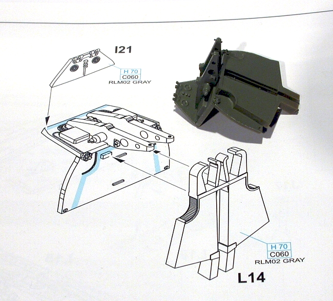
I'm not sure if it's normal for the wheel well top part to want to be off-center laterally, but mine did. That places the little tube triangle between the wells a little off center, too. One critical consideration is that the wheel well top has notches to locate the engine mount. You really want that as centered as possible. The fronts of the well top piece fit snugly within the top wing surfaces, and can cause problems getting the top and bottom of the wing to fit without gapping, so it pays to get the wheel well top to fit perfectly. It should not cover any of the mating surface for the leading edge top and bottom surfaces. Just behind that mating surface is ideal. If you need to fit it, it is best moved rearward by filing the points where the wheel well top meets the spar. Check that the slot that is left between the well top and the spar will accommodate the bottoms of the cowl gun ammo chutes properly. The ammo chutes should be a snug fit, but should pass through the slot, so get the ammo chute part L14 and check that. If everything is to your satisfaction, glue the tube triangle and the well top in.
Here is where you need to decide if you are going to close the wing gun bay covers. You will need to cut away a crescent of plastic from the rear of the opening in the wing top surface if you are. Cut this a bit smaller than Eduard indicates, then file the rear part of the gun bay covers nearly flat. Fit and file until these look as good as possible when test-fitted. Don't expect miracles. I had gaps in front and to the sides of the covers. I just closed the gaps with white glue after the final attachment of the covers, which shouldn't be done until wing and fuselage have been glued together. I left the bottoms of the wing gun bays out, which leaves open ejector chute holes in the bottom of the wing. That's a small price to pay in order to have access to put a paintbrush handle or toothpick up through the hole so upward adjustments to the gun bay covers can be made when you are gluing them in place. Nope, this one didn't catch me. I thought of it as I was filing and fitting the covers before the wing was assembled, since the way the rear of the covers fit tends to exert a pressure which pivots the front of the covers down below the wing surface
There are three location points which have everything to do with how the tops and bottom of the wing fit together. I have labeled them in my little photo…
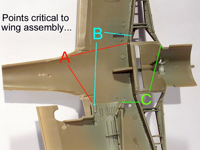
Point A locates the relative lateral position of the top wing surface and the spar. This defines the width of the wing root area. I found I was happy to make this fit a little loose, and just count on the correct fit of the top and bottom at the wingtips for alignment. It is a good gluing location nonetheless, so if you need to adjust the wing top sideways to fit correctly at the tip, and there seems to be something interfering, it is probably the fit at this point. Just file or carve enough to get the wing tips to align top and bottom, side-to-side.
Point B defines the wing thickness at the root. If the top and bottom of the wing are not spaced properly here, the fit to the fuselage wing root will suffer. Tape the fuselage halves together and check the wing root thickness with the top and bottom of the wing dry-fitted. Mine was fine, and required no adjustment, but point B is where you would file or shim if necessary.
Point C is simply the wheel well roof and upper wing surface interior junction. I had to do a bit of filing here to get the top and bottom of the wing to fit nicely at the leading edge. If the upper wing surface seems to want to locate forward of the lower surface at the root, and efforts to move it back result in the wingtip losing the fore-aft fit of the top-to-bottom surfaces, then point C is worth checking.
If the top surfaces of the wing fit well, giving no gaps, and test-fitting the taped together fuselage halves shows a good wing root thickness fit at this point, you're in business. Make sure you consider if you need to open holes for rockets…(I forgot), make sure you make a hole for the pitot tube so you can avoid drilling one later and cracking the wing leading edge seam open… (I cracked it open), and glue the wing tops onto the bottom.
(Note; “Uschi” did not have a drop tank. Drop tanks and inner gear doors were mutually exclusive. I saw a picture of an A-0 with the doors and the tank, but that's the only one. Didn't look like it worked too well, either.)
I didn't install the wing root cannons until after the model was painted. They are flexible enough that you can actually squash them in from inside the wheel well. You might want to open the hole just at the front of the wheel well for them a bit to facilitate this squashing maneuver if you choose this method. Surprisingly, it worked fine. Didn't break the barrels or anything.
So…if you needed to make significant adjustments at points A, B, or C… you might have a small alignment problem. Eduard placed these points pretty well. My needing to fiddle with point A might have told me my spar was slightly off-center.
Just imagine how much test fitting you'd have to do quickly enough that the glue hadn't set on the spar by the time you test fit the wing upper surface and got an indication the spar was off-center. That's the nature of this kit. If everything aligns perfectly during assembly, you have nothing to worry about. The molding of certain locating points, though, allows enough play so that perfect alignment isn't a foregone conclusion. You've got to be alert!
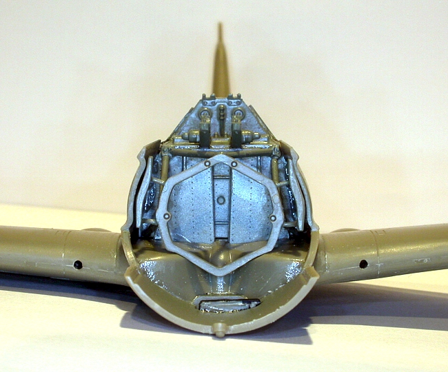
Now that we have a wing, it's time to build the fuselage. Yes, there are some considerations here. These stem almost entirely from the firewall/bulkhead assembly. This assembly and its subsequent fit into the fuselage are the worst combination of critical-to-the-build and engineered-to-cause-difficulty of anything in the kit.
The problems with the bulkhead assembly are almost exclusively from vague locating points. I honestly believe this could have been done a lot better. When assembling the bulkhead itself, you are expected to achieve two right-angle joints. No, there are no alignment aids molded in. Just butt joints.
I thought what the heck, I'll stick the parts together and lay them in one of the fuselage halves to align them with the place the assembly goes, and that way everything will fit fine. That's when I found out the edges of the bulkhead parts only approximately match the shapes of the places they are to fit in the fuselage. The bad fit actually leaves some of the locating tabs unable to reach the bulkhead parts!
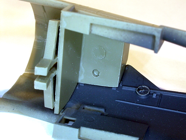
Drop the cockpit assembly into a fuselage half. Tape the fuselage halves together. Take your set-up bulkhead assembly and dry-fit it where it goes. Make your best guess. Fit the taped-together fuselage to the wing assembly. Remember the ammo chutes fitting the slot in the wheel well top? How are the wing roots? How's the alignment of the fuselage bit ahead of the wing roots? Hopefully, it's all not too bad at this point. The fuselage may be slightly narrow for the wing roots. Mine was not bad, but then I checked how the bulkhead fit in the fuselage. Oh, brother! There were about two points where the bulkhead actually touched the fuselage sides. The rest was hanging in mid-air. That will never do.
I solved the problem of deficient contact area by gluing a strip of .030” Evergreen strip plastic on each side of the main bulkhead piece and filing/sanding it back by stages, test fitting all the way, until everything fit nicely when the fuselage just clicked into the wing roots. It's a good idea to check the fit of the windshield and cowl gun cover, if you're closing it, at this stage, too. (If you haven't already, nip the four cowl gun ammo feeds off for closing the cover.) I found that when the windshield and gun cover fit the fuselage sides best, there were gaps between the upper bulkhead and the fuselage sides. Since I knew I was closing the gun cover, I just fitted the main vertical bulkhead and, after I knew the windshield and gun cover fitted up, and only when I had everything ready to close for good, filled the gaps that occurred above that with white glue for some solidity. If you are opening up everything, it would make it look better to continue the strips of Evergreen all the way up the sides of the bulkhead assembly and sand and fit that, too.
I caution about waiting on the white glue filler if you so choose, or actually applying cement to the very top bulkhead part to fuselage points because I had to break the top bulkhead part off and re-align it at a late stage to get the best windshield and gun cover location. I also ended up bending the tiny hinges at the top of the bulkhead forward a bit so I could slide the windshield forward for proper fit. This whole assembly process will absolutely make or break the appearance of the finished model. Take your time.
After you are satisfied that you have the edges of the bulkhead assembly shimmed properly to ensure best fit of wing roots and ancillaries, it seems appropriate to glue the fuselage together. First, though, pick a tailwheel. I used the multi-part one. Once I saw the fork legs on the real tailwheel were not parallel, but pinched in at the axle, I figured it was okay, so I used it. I don't like the way it has to be installed as you are gluing the fuselage halves together, because there is a chance it may come loose later and you will need to fire liquid cement down the blind hole trying to re-secure it after the fuselage is assembled. Umm… Yep. I did it.
Secure the tailwheel into a fuselage half, and attach the cockpit. Only apply cement to the cockpit rear deck. Don't put any glue on the cockpit floor where it slips into the sockets molded in the fuselage halves. These will take care of themselves, and leaving them loose just lets the rest of the width adjustments you made to the bulkhead assembly do the job of controlling the fuselage width.
Since I knew access would not improve from this point, I used the burr on the Dremel to clean out the points on the bulkhead where the tubular engine mounts fit. This little operation also gets you familiar with how those points are laid out. I wonder if this couldn't have been handled a bit better by Eduard. Locating pins on the ends of the tubes which locate into holes at the mounting points would have provided a more secure fit, as well as minimizing the possibility for an error when smoothing the places on the ends of the tubular mounts where they were removed from the sprue. It is possible to remove too much or too little material and affect the length of the engine mount. If there were pins molded on, things would have been much simpler.
Finally, glue the fuselage halves and main bulkhead together, tape the fuselage halves, and click the fuselage onto the wing. Here's where the care you took making sure the bottoms of the ammo chutes fit into the slot in the wheel well top/spar assembly pays off.
Things really should “click” fit with nearly invisible seams all around if you have done well with all your fitting. Set the model aside and go relax. You earned it.
Note, at this point you should not have attached any engine mounts, nor the engine to the mounting yoke. The windshield will fit “pretty close”, more than likely, and the gun cover likewise.
After the fuselage is secure and the glue has set, you may glue the wing to it. Stiff upper lip and don't forget the tape!
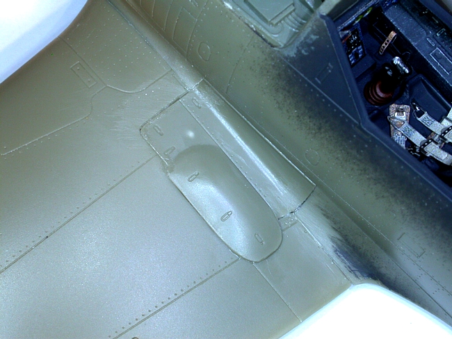
At some point you will want to consider whether you need to remove the mount for the D/F loop from under the wing. It's easier before you paint the model. How do I know that? Oh, yes… sometime it would be good to paint and install the bottom exhaust pipes so you don't forget them.
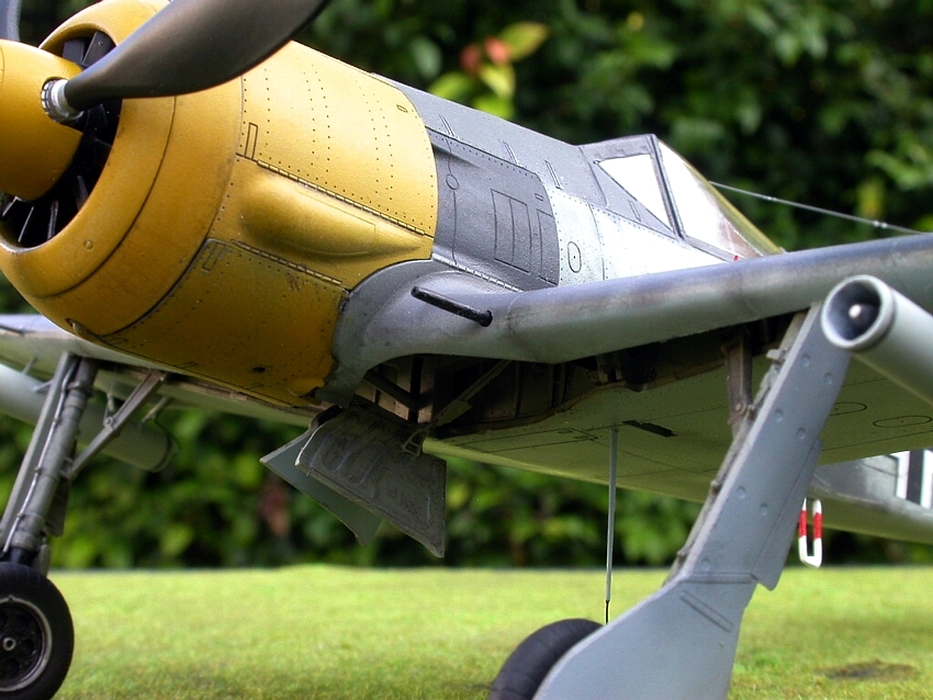
I found it sensible to make up the cowl and adjust the fit of the gun cover and windshield first, and place the engine mounts and such after, since the relationship of the position of the engine and the various exterior pieces will affect the position of the cooling fan and the propeller. The kit parts seem to favor having the cooling fan and propeller (meaning the whole engine) a bit too far forward. Perhaps if the tubular engine mounts were adjusted for length appropriately, this would not be the case, but it is very difficult to adjust them. Once the fuselage is assembled, the mounts are surrounded on three sides by fuselage, and unless you have the uncemented parts located precisely, including the engine mount yoke, you can't really gain any useful information on just how things do fit. So… We'll simply do what we can.
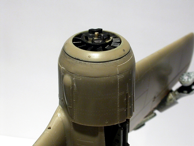
To assemble the cowling, and help the appearance, I wanted to have the rear of the part with the gun troughs to be as high up as possible without leaving too much edge showing at the rear. I filed the locating flanges on the sides of the part thinner at the back, making them wedge-shaped. That raised the back a bit. Every little bit helps…
The cowling ring that meets the cowling side pieces has a locating aid to center it on the side piece assembly. It located the top cowl panel off-center to the scribed lines on the ring. One place Eduard provided positive locating assistance, and it had to be changed. Not a big deal, but the personality of the kit shines through again. (I developed a fondness for this kit as it came together similar to the feeling General Sherman developed for General Johnston in the Atlanta campaign of 1864. I respect its wily nature, but I will beat it!)
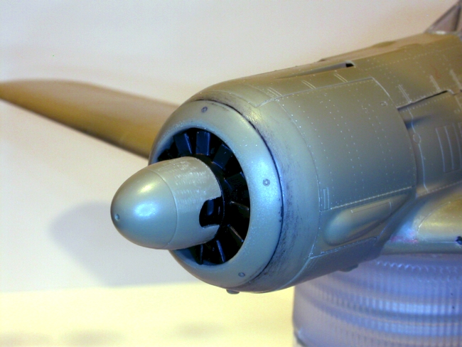
The very front of the armored oil cooler ring is molded fairly sharp in the kit. The real plane's front edge here has a nice radius. I sanded the front lip rounder. Another little thing that adds to the cumulative effect to improve appearance.
Tape the cowling together and check the fit on the nose. I had to file the area on the bottom where that little oval protuberance fits into the slot in the cowl ring, deepening the slot a bit to get the cowl back as far as possible and minimizing the fore-aft gap between the cowl bottom and the cowl ring.
If it looks like everything on the cowl lines up, and the fit has been adjusted to your satisfaction, glue the cowl parts together and set the cowl aside.
If you are closing the cowl gun cover, get a little round file and deepen the places on the inside of the cover where the gun barrels will go. You need to slot these places out to prevent the cowl gun barrels from pointing up at an alarming angle. Chances are, you will be attaching the gun barrels to the inside of the gun cover as I did, so shape accordingly.
After that is done comes the work of getting a good fit for the gun cover and windshield to the fuselage.
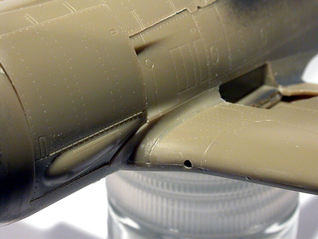
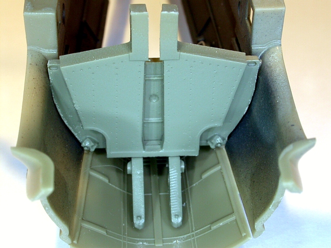
When I first taped the fuselage and nose parts together, way back when I first started this kit, I got the impression that something was not quite right in the appearance of the area from the windshield forward. The model, if assembled with unmodified parts, seems to have a “sway-back” look to the top of the nose. The gun cover fits a bit high at the windshield. If care is taken to lower the gun cover at the windshield, a lot of that appearance can be corrected.
In the accompanying photo collage, I attempted to illustrate the process of making the small adjustments to the windshield and gun cover area.
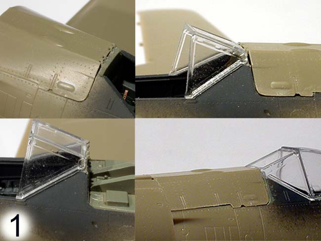
With these small cosmetic adjustments, the appearance of our 190A-5 is certainly improved. No big deal, just a bit fiddly.
I found it a good idea to cement a couple little plastic tabs to the front of the gun cover inside which will help align the edges of the cover with the fuselage sides. I made them from .030” strip. The gun cover will go on before the cowling, and be slid on from the front to get those tabs inside the fuselage sides. With a bit of tweaking, the tabs should center and align the front of the cover nicely.
Okay, we have a fuselage and wing. Might as well put the wing gun covers on. You might notice that the cutout in the fuselage part of the wing root doesn't exactly align with the cutout in the wing. I chose to file the areas until things aligned pretty well. Keep on test fitting until you have the areas massaged as well as you might. Probably, if you're closing the covers, you will notice how nice it is to have access to beneath the covers by sticking a toothpick or whatever through the ejector port under the wing since you left out the gun bay floors…
Once you are happy enough with the fit of the covers, glue them on. I had a gap around quite a lot of the cover that I filled with a few light applications of thinned white glue on a brush. Ultimately, this didn't look too bad at all.
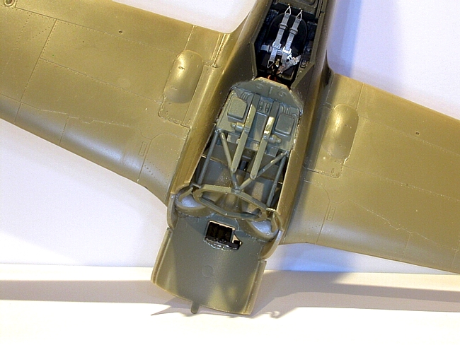
Now for the engine mounts. Three hands come in handy for this. One for holding the part with tweezers, one for holding the model, and one to hold a small flashlight so you can see what you're doing. I only have two hands, so I fumbled around in the dark until I got them all placed reasonably well.
I first attached the three tubular supports to the engine yoke part, made a couple stabs at lining them up while the glue was setting, then applied glue to the back ends of the tube parts and placed the ends as well as I could with tweezers while the glue was still wet. Sitting the circular yoke part in the notches provided for it in the top wheel well part helps. After I had the tube parts in their sockets on the bulkheads, I checked that the yoke was seated into the notches and flooded the attachment points there with liquid cement on a micro-brush. I noticed my yoke did not seat clear back in the notches. Hmmm?
Perhaps if you were to cement the tubing parts of the engine mounts to the yoke part when you still had the bulkhead loose, so you could place the back ends of the tubing parts in their mounting points, thus making a pre-aligned assembly of yoke and tube parts, it would allow you to fit and adjust these parts for length better. The only problem I can see with this idea is that you'll have to figure some way to get that wheel well top with its locating notches into a proper relationship with the bulkhead in order to have something to shoot for when adjusting the general orientation of the yoke/tubes assembly before the glue sets on them. This would require accurately dry-fitting and taping the fuselage, bulkhead, and wing before the glue sets on the yoke/tubes assembly, but after they were set enough to hold their orientation from aligning them with the locations on the bulkhead, which you had loose and free in order to have an advantage in visibility/access… May I venture to say, this is a very troublesome assembly area in this kit.
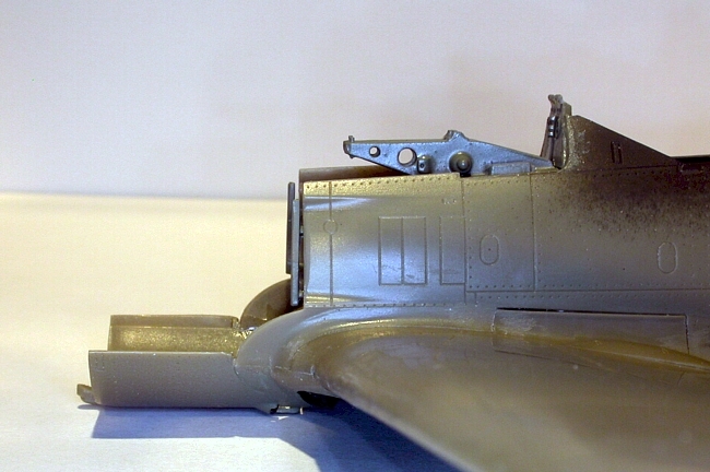
The yoke part has a couple “wings” sticking out to the sides which locate just forward of the front edges of the fuselage sides where the exhausts exit. If these are aligned vertically with the edge of the fuselage and pretty even from side-to-side with the fuselage sides, you've done well with your work.
Now you have a fuselage and wing with the engine mount in place. The fit of the windshield is perfect, as is the fit of the cowl gun cover, of course. The cowling is assembled, as is the engine. So…
I rigged a set-up with my little “extra hands” gator-clip thingie so I could stand the model on its tail. Then I stacked the engine, cowling, and cooling fan together on top of this to check how things looked for length and fit relationship. The calibrated eyeball told me I would have to move the engine back “a tad”. (Where's my “tad” ruler?)
There are four pins on the back engine plate that locate the engine on the engine mount yoke. I cut them off and filed all the little cylindrical mount posts to shorten them. This moved the engine back almost enough. The remaining extra length was taken off the crankcase and back of the cooling fan. Test fit, test fit… etc. Perhaps if I had seated the engine mount yoke back all the way in the notches in the wheel well top. Well, re-read the above section regarding the fitting of the engine mounts.
Test fit, test fit…
Ultimately… not bad!
Okay, brave ones; we can now put the front of this thing together permanently. Place the model back in your rig for sitting it on its tail. Now, apply cement to the ends of the cylindrical mount posts on the engine back plate and place that engine on the mounting yoke as accurately as you can.
Then quickly slip and tape the cowling on and place the cooling fan on the crankcase. Don't glue the cowling or fan… just place them in their locations so as to ensure the engine dries attached in a correct orientation for length and centered in the cowl opening. Let this sit until all is set up.
When the engine is securely in its mounting, you can take the model out of its vertical support. Remove the cowling. Snip a length of barrel off the cowl guns and attach them appropriately to the underside of the cowl gun cover in those grooves you filed earlier. Note; check photos to see how much gun barrel sticks out from the front of the cover. The A-5 had a longer cover than the A-4, but the cowl guns were in the same place, so less barrel sticks out from the front of the A-5's cover than the A-4.
While the glue on the barrels is still not set, slip the gun cover with attached barrels onto the model. Slip the cowling onto the model. Adjust the location and orientation of the gun barrels so alignment with the troughs looks proper and let the barrels dry in place.
Are you ready? Go ahead and glue the gun cover and cowling in place. Say goodbye to the engine first… you'll never see it again. I toyed with the idea of leaving the cowling loose, and since I can actually remove my propeller and cooling fan assembly, I might have gotten away with it. That way I could have removed the cowling to see the engine. But… nah. I wanted the cowling to be seated as securely as possible, so I glued it and taped it tight to the model to minimize seams.
The last potentially troublesome assembly is the landing gear. If you aligned the spar correctly, this should be a breeze. If you got the spar off center, like I did… you will have trouble. The one side that was located too far inboard gave me no problem. The other side, however, required that I cut the nub off the end of the landing gear leg, cut the alignment rib off the back of the leg, and carve the inboard side of the socket on the spar open more to allow the leg to locate at the proper angle.
I found the landing gear doors to be a big help when placing and aligning the gear legs. Do locate them on the legs as Eduard describes and have them on the legs before you glue the legs into the sockets. Once assembled and the scissors links in place, things are pretty sturdy.
I stuck the wheels on the axles with the good old slow drying plastic cement after flattening one side of the tire for scale weight effect, and just sat the model on the wheels, sliding a little square glass paint bottle against each wheel to square them up vertically and ensure the toe-in angle stayed consistent. No sweat.
As the wheels, so the horizontal stabilizers. They fit loose. Stick them on with slow-drying plastic cement, prop them up at the correct alignment, and let them dry.
Oh, yes… After the camouflage and the wing cannon were painted, the cannon barrels were squashed in place. It is a good idea to do that before you attach the inner gear doors and such. Speaking of inner gear doors, check out that you have two options for the actuator links. One is a styrene stick, and the other is a fairly complex photo-etch assembly. The instructions show the photo-etch one locating to a different spot on the door than the styrene one. Don't believe it. The location on the door for the styrene actuator is correct for either one you use. I might also mention that Eduard shows the separate pad that locates on the photo-etch actuator link being placed reversed. The big end goes where the small end is shown.
There are many things I have not dwelt on because they are easy. The canopy fits, the ailerons just need a little common-sense fitting, and the remaining things don't really cause trouble. If you have persevered, you will have the hard parts whipped.
I would like to mention the WGr.21 rocket assemblies, though. The supports provided in styrene are useless. Eduard also missed the fact that there was a central hanger point on the rockets. (They missed this in the Bf 110G-2 kit, too…) I made a central hanger from sprue, drilled holes for it, and attached the rocket tubes to the wing with that. Then I stretched some sprue fairly thin, and cut it using the Eduard provided blobs to give me approximate lengths. Those became the sway braces on the sides of the tubes.
I made a pitot tube from a piece of stainless tubing that was sold as material for 72nd scale 7.9mm gun barrels. Makes lousy gun barrels, but it makes a good pitot. A bit of sprue stuck in the end, and instant pitot. (The Eduard pitot was as useless as the WGr.21 sway braces…)
I purposely avoided giving all the gory details about what to paint, when to paint, and other such things. Once I got my rationale for the camouflage scheme out of the way, I imagine everyone has their procedures.
Conclusion
This kit could have been a knockout with only a few points to trouble it; (the vertical fin thickness, the short cooling doors behind the exhausts, the strange propeller blade shapes among the more notable), but the real difficulty appears to be that the molding process was not capable of holding the precision necessary in the vertical plane of the mold or in the smaller cavities to make the optimistic engineering concepts work. Assembling this kit is too much like a brain-teaser.
I should mention, also, that any reference photos of the real thing, and of specific parts thereof, will be of great assistance. The instructions are, in some cases, insufficient guide for the correct placement and configuration of items in the kit.
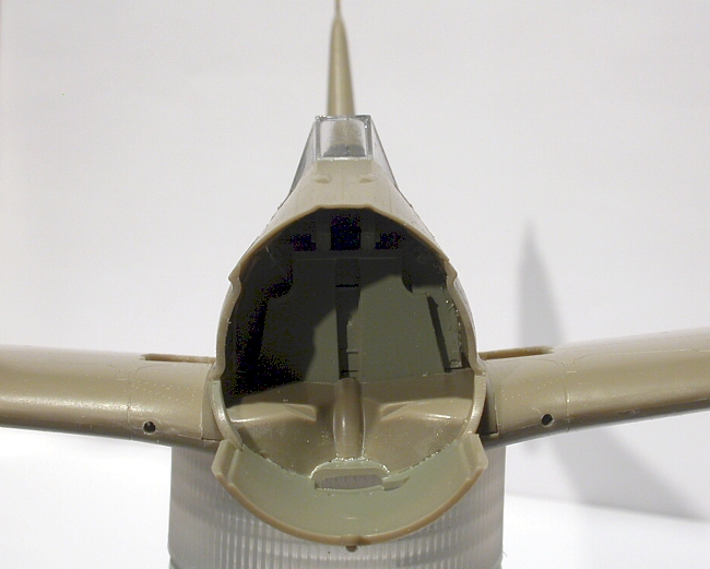
The end result is potentially very good, though. I hope I have been able to demonstrate that with my photos. If you like a real challenge, and if perhaps you find my article helpful in unraveling the difficulties, this kit is actually kind of fun!
By thunder, General Johnston… I have soundly whipped you!