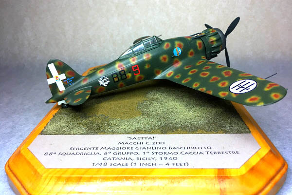
Sicilian Lightning: Building the Special Hobby 1/48 Aermacchi MC.200
By Ralph Nardone
In order to save space, you can see my in-box review here:
First Look: Special Hobby 1/48 Aermacchi C.200 I.Serie Saeta in 1/48 scale
A few things to take away from the in-box review. First, this is a limited run kit and you will get out of this kit precisely what you put into it in the form of parts preparation, added detail, and research. Second, there are a few "options" not listed in the instructions that you'll have to keep in mind—the rudder, roll over structure, and prop spinner may or may not need to be modified depending on which airplane you wish to model. Third, I find kits like these more interesting to build than a "box-shaker". I have to do some planning and research at almost every stage of the build, and I have to be flexible enough to change those plans as the build progresses. What may seem acceptable at first may later be found to be inadequate and new parts may have to be produced.
I deviated from the "out of box" rule in order to get a better model, but did not delve into super- or hyper-detailing the model. The techniques I employed are not difficult at all—all you need are some scrap wire, plastic rod, sheet plastic, metal tubing, patience, and time. I will bet that 99.9% of the modelers reading this are capable of successfully adding the same enhancements I did. All one needs to do it get their mind right and realize they can do this. As soon as you say "I can't" is when you won't.
 I removed the casting blocks from the resin parts and cut the major plastic parts from the sprue for a test fit. As is usual with limited run kits, the trailing edges needed to be thinned and the mating surfaces needed to be dressed. I accomplished this by rubbing the parts on a sheet of 400-grit sandpaper as you would a vacuum formed part. On some of the trailing edges, I thinned them from the inside as much as I could, and took care of refining the thinness once the halves were assembled. This is particularly true of the rudder—you can only thin it so far from the inside before you begin to alter the shape of the rudder itself. Since there is more meat on the outside, do your final thinning then. Any surface detail—in this case, rib tapes—can either be totally removed (if you find such detail unrealistic) or replaced with thin strips of Tamiya tape or Bare Metal Foil. Once I was happy with the surfaces, I set the plastic parts aside to deal with the resin.
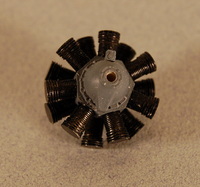
The kit engine is a simplified assembly. The engine crankcase was painted blue-gray, and the cylinders were painted flat black. When the black paint dried, I buffed the cylinders with an SNJ polishing cloth to enhance the fin detail. The cylinders were attached to the crankcase with small drops of super glue—they aren't quite correct as the kit parts omit the cylinder heads. I decided to let sleeping dogs lie in this scale, since once the engine is assembled into the cowling you can't really notice it.
I did add pushrods to the front bank of cylinders since they are prominent—they were fashioned from lengths of .025" Evergreen plastic rod, painted silver. A quick test fit into the cowl ensured that all was still good. You could go nuts adding detail to the engine, as there is a lot in there. The more masochistic modeler would probably want to hollow out the clearance bulges, revise the cylinders, and mold proper cylinder heads as a start.
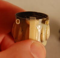
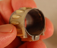 The cowling wall wasn't equal in thickness and this will prevent the engine from fitting inside. I took my trusty motor tool and ground out the inside of the cowling until the engine was a slide-fit into the cowl—this is important, since the cowl does not have an integral means of attachment to the airframe. The engine is what attaches the cowl to the fuselage, so it should have a close fit within the cowling. Incidentally, most radial-engined airplanes are like this—the engine attaches to the bearer, the forward cowl ring attaches to the engine, and the cowl panels bridge the gap.
While I had the motor tool going, I also drilled out the exhausts in the cowl and a hole for the prop shaft in the engine crankcase. A light sanding inside the cowl to smooth out the grinder marks, and it was ready for paint.
Leave the engine and cowling separate until after the cowling gets painted. It makes finishing the cowl easier.
 Now that the cowl and engine were complete, I moved on to the cockpit. Not much to report here. I first shot a coat of PollyScale British Interior Green onto the cockpit parts. Details were picked out with a small brush and various colors, using reference photos as a guide. The cockpit is fairly complete, and not a lot can be seen once it is assembled and installed, so I pretty much kept to what the kit gave me. Beware, though—the instructions have you try to install the instrument panel after the cockpit is installed and the fuselage is assembled. It won't work that way—install the panel when you assemble the cockpit capsule. I didn't, and the instrument panel in my model looks like it sits a tad low—I tried to fix it, but was unable to do so without destroying it. I'm telling you this so you won't make the same mistake I did.
I zipped up the fuselage, and then tacked the cockpit assembly in place. It was easier to do that since there are no positive locators for the cockpit molded into the kit. I could maneuver the cockpit assembly around until I had it in precisely the right place before I permanently attached it.
The engine truss was built up to the resin bearer and attached to the bulkhead/wing spar—it took some test fitting and trimming to get everything to fit properly—those truss sections don't seem to be totally symmetric, and to do a decent job, you will want to "fish-mouth" the ends of the members that touch with a round file. The truss/bulkhead assembly was painted with PollyScale British Interior Green—it is a decent match for Italian Verde Anticorrosivo.
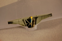 Now comes the fun—have you ever looked at photos of the gear wells in a WWII Italian fighter? They are positively crammed with wiring and cables. Also, there is a lot of structure in there, structure that the kit didn't give you (the oil tank) or didn't quite get right (the bridge part across the forward end of the gear well). I used some wire and styrene tube to add some life to that area—I didn't duplicate everything wire for wire, I added enough to make the area look busy. The wiring and piping on the 1:1 was color coded—yellow for fuel, brown for oil, blue for electrical, red for pneumatic, etc. After picking out the various colored wire and tubing, I added a few structural members that the kit didn't give you. There is more fun to come with the main gear wells, but that will wait until we've assembled the wing parts.
The engine bearer/bulkhead and wing spar was slid into place and attached to the fuselage. I test fit the wings by taping the halves together. This is one of those kits that would benefit from having the upper wing halves attached to the fuselage first, letting the glue dry, and then adding the lower wing in order to minimize gaps. I tacked the upper halves in place to the fuselage, and then offered up the lower wing to see how things were. I found that I needed to take some material off the lower edge of the spar. While I was at it, I thinned all the way around the edges of the gear well. As you assemble the wings, maintain proper alignment--the wing needs to be square to the fuselage centerline when viewed from above, and the wing dihedral needs to be equal. In my case, the port wing wanted to sweep back. I popped the port wing top loose, sanded the wing root to get the wing to match the angle of lower wing, and then re-tacked it in place. Once you are satisfied that the wings are aligned properly, attach them to the fuselage and install the lower wing half. I used some super glue tacks to hold things in place, and then applied liquid cement. I also used some styrene shims to fill some gaps at the leading edge root area on both wings. I built up some sink marks with small drops of super glue as well. Once the wing tops are set, install the lower wing and cement in place. I wound up with some misalignments at the wing tips, but I sanded them to the proper profile and re-scribed the missing detail later.
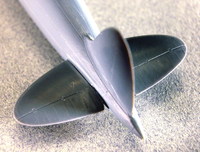 While things were drying, I did another alignment check (remember the Three Kings of scale modeling: Straight, Square, and Plumb). I propped the model up on some paint jars and ensured that the vertical tail was indeed vertical and that the wing dihedral was properly set—rather than measure the wing tips, though, pick a reference point about mid-span on the wing. If you use the wingtips, the geometry of the airplane will be off due to the (correct) wing length difference described in the First Look. I left this assembly sit so the cement could harden.
The horizontal tails were tack glued in place with a drop of super glue and their alignment verified. Once I had everything straight and square, I filled the join lines with thin superglue. I slowly filled the joints and any gaps with the superglue, and once it had dried I sanded the stab roots while the glue was still relatively soft—I didn't want to wait too long and find out I needed a diamond grinder to eliminate the seams. I don't normally use super glue to a large extent in my model building, but in cases like this the fast setting times make life easier. (Note: That was then--fast forward 15 years, and super glue is now the first filler I reach for. Did I perhaps become older and wiser in the interceding 15 years?)
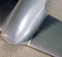 If you are careful, you won't need any filler at all—the fit was quite good. I only needed filler where the wing leading edges joined to the wing root and at the trailing edge/fuselage junction so far. My choice for filler varies—for really large gaps, I'll use plastic shims or epoxy putty. For smaller gaps, thinner shims or Squadron White putty do the trick. For hairline seams, I'll use Mr. Surfacer or super glue. For the gaps I had on this model, I used a combination of styrene shims, white putty, and thin super glue. (See my note above—my filler choices have changed. No longer do I use any sort of lacquer- or solvent based fillers, opting instead to use super glue, epoxy putty—Apoxie Sculpt in my case—or Evergreen strip and rod.) [Photos: wing shims, belly]
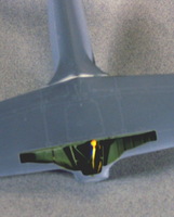 I re-scribed panel lines that were shallow or removed when I dressed seams with a sewing needle chucked into a #1 knife handle. While I had the scriber out, I revised the rudder hinge line. Photos of the airplane I modeled show the rudder to have the straight hinge line and the roll-over structure present under the rear canopy—details that are important because they are usually determined by the paint scheme you choose. If you are one who must have absolute accuracy (i.e., the specific doo-dads that determine which production block an airplane was built under), you'll know to nail this down before you start.
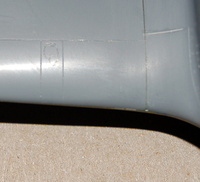
The attachment for the main landing gear struts as presented are weak at best—there is a shallow dimple in the wheel well, and a pimple on top of the gear strut. This is not conducive to a sturdy model. You could make wire or styrene pins to get a more secure attachment, but I decided to add some trunnions made from sprue. Follow along:
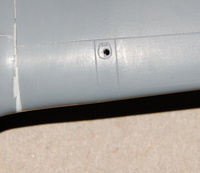
I took a section of kit sprue that looked to be about the correct size—I didn't measure, I merely eyeballed it to make sure it was marginally wider than the strut tubing diameter--and sanded a slight flat onto one side so it would fit in the wing. I cut the sprue to length and adjusted the fit until it slid into place at the outboard end of the gear well, shimming as required to keep it level with the wing. To index them properly, I drilled through the dimple in the well and straight through the top of the wing. The trunnion—the sprue we just shaped--was installed and secured with super glue.
|
|
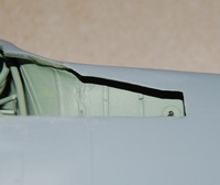
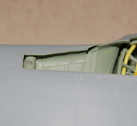
Once the glue had dried, I match-drilled through the hole I drilled through the top side of the wing down through the trunnion. I then drilled from the well side of the trunnion with a larger drill, one the same size as the strut. Drill only deep enough to accommodate the strut—drill a little bit, set the airplane on the gear, and then adjust the holes so that the gear is the proper length and exhibits the proper rake and the airplane sits level on the struts. Once you have everything right, plug the hole in the top of the wing with a bit of Evergreen rod or stretched sprue.
|
|
While it sounds tough, it took longer to write about it than it did to actually do it. Now, the real question—is it 100% per the prototype? Not quite, but it looks better and is more secure that the simple butt joint that the kit gives you.
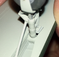 I added strut well liners from paper soaked with thin super glue. This goes a long way to improving the look of the gear well area, since it is such a busy area in the prototype. The paper becomes almost like plastic, it is flexible, and is quite useful.
I really didn't like the main gear struts as-molded and debated whether or not to scratch-build a new set. I tried to clean up the kit parts, but they suffer from several issues. They are soft, and had some serious mold misalignment problems. When I tried to clean them up they wound up having an oval cross section. It seemed as if new struts were in my future. Again, follow along:
I found a piece of aluminum tubing in the junk box that matched the diameter of the strut oleo. I cut this to length (I measured from the top of the wheel forks to where the struts would be installed in the trunnions) by rolling it under a #11 blade until it separated and then I cleaned up the cut ends with some 600 grit sandpaper. I then cut the wheel forks off of the kit parts and drilled the strut location out. The aluminum tubing was then attached to the forks with super glue. I cleaned up the forks with files and sandpaper. To simulate the actual casting of the strut, I rolled paper from a legal pad around the tubing until I achieved the proper diameter for the strut, and secured this with super glue. Once the glue dried, I lightly sanded the end of the paper to blend it into the strut. The raised bands on the strut were also made from strips of paper. Remember to take into account the height of the trunnions made earlier, or you will have to go back and re-wrap the tubing. The bare, unpainted tubing itself is perfect for the oleo section.
I drilled the forks on one side for the wheel axle. The wheels had axle holes drilled into them, and then I used a bit of stiff wire as an axle. I inserted the axle through the hole in the fork, inserted the wheel, and once the wheel was straight and square in the lower unit, I drilled the opposite side. Once I had everything where I liked it, I disassembled the wheels, axles, and struts, keeping track of what went where. The parts were then painted and allowed to dry. Once the paint had set, I assembled the wheels and axles to the forks. A disc of plastic covered the axle holes on the inside fork of the lower units-the outside forks are hidden by the wheel doors, so I didn't waste the effort. The resin strut scissors were installed, and the struts were touched up and set aside for final assembly.
The manufactured set of struts is crisper, stronger, and will support the model much better, in my mind, than the kit parts. Again, it is not 100% accurate, but it looks good, and for me at least, looks are what matter.
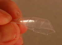 The canopy was carefully cut from the backing sheet. Use a brand-new #11 blade, and go slowly—it should take a dozen or so passes with the knife to cut the part free. Remember, with clear vacuum-formed parts you don't have the luxury of using filler to fix your goofs. Having two canopies gives you a little bit of security—it also enables you to open the canopy without having to worry about how precise your cuts are—but still be careful.
Before the canopy is installed, attach the roll-over structure behind the cockpit opening (if the airplane you are depicting had it) and shoot a quick coat of the Verde Mimetico camouflage color in the area of the top of the fuselage that would be covered by the canopy. The canopy can be installed now--I use Pacer Technologies' Formula 560 Canopy Glue for all of my clear parts. It is stronger than white glue, and dries clear. It cleans up with water, too, and I have actually used this to fill small gaps. I masked the canopy with Tamiya tape (great stuff, by the way—if you don't use it, you should give it a whirl) and shot some Verde Anticorrosivo on the outside to portray the frames. For those of you that want to open the canopy, you'll want to paint the frame lines on the inside—it just looks better.
I checked the seams once again to make sure I had caught all of the gaps, scratches, gouges, and glue boogers. The last thing I did before paint was to stuff some tissue into the gear wells (this would be a waste of effort, as we'll reveal later). A quick wipe with some Isopropyl Alcohol, and I was ready for paint.
Applying the paint scheme was an adventure in and of itself. Painting Italian WWII schemes can be as challenging as a Luftwaffe mottle scheme. I decided to do the aircraft of ace Sergente Maggiorre Gianlino Baschirotto, which is painted in the "poached egg" or "fried egg" scheme of Verde Mimetico 2 with splotches of Giallo Mimetico 4 with Bruno Mimetico centers over Grigio Azzurro Chiaro 1 undersides. The markings are provided with the kit.
I have read different modelers' methods on doing this scheme—one modeler paints the whole upper side Giallo, then adds the Bruno, then finishes with the Verde. Another shoots the green base, then adds the spots. Some use stencils, some do it freehand. The only way I could see getting it done was to follow the Nike ad's advice—Just Do It.
As it turns out, I "just did it" six (!) times before I got a result I could live with. Rather than bore you with my failures, let's move ahead, shall we?
All of the camouflage colors were matched as close as I could to Vallejo's Surface Primer, Model Air, and Metal Color ranges. I use Vallejo's 71.161 Airbrush Thinner and starting ratios of 8-10 drops paint and 2 drops thinner to Model Air paint or 6 drops paint to 2 drops thinner for their Surface Primers. The Metal Color line doesn't need thinning. For mottling, I'll add a drop more of the airbrush thinner plus a drop of Vallejo's 70.524 Thinner Medium. I'll do a test spray and adjust the pressure and thinning as needed.
I painted the bare plastic and had no issues. I find one of the keys to Vallejo is to build up the color using several light coats rather than hosing on one heavy wet coat. If you feel the need to prime, by all means, do so. If you are a fan of black basing, Vallejo's Panzer Gray Surface Primer is a good base, but again, you use what makes you comfortable.
I painted the leading edge of the cowling with Metal Color 77.723 Exhaust Manifold. After it dried, I masked the oil cooler inside and out, and then painted the cowl interior with 71.277 Dark Gull Gray. The underside of the airplane was painted with a mix of various Vallejo grays (Dark Gull Gray, 71.296 Curtiss Gray, and 71.103 RLM 84 in a 1:4:8 mix) that was close to Grigio Azzurro Ciaro. After re-consulting my references, a lot of photos of the subject airplane seemed to indicate that the landing gear struts and wells were painted gray, too, so I made the change while I was at it. So much for the tissue masks, huh? In the end, I didn't even bother to re-paint the wires and lines I added, since, with the model attached to a base, they'll very seldom be seen anyway.
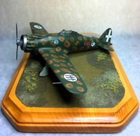 I masked the lower surfaces and painted the top with 71.219 RAL 6007 Dunkelgrun. I allowed the green to dry for several days and next added the Giallo spots using 71.025 RAL 7028 RAL Dunkelgelb. It took a while to get the thinning ratio and air pressure dialed in, but by the time I was done, I finally had something I could work with. I added the small shots of red brown using 71.217 RAL 8012 Rotbrun.
I don't care what paint I'm using, there are times when I need to deal with overspray, and this was no exception. I made a highly thinned mix of Verde and used it to touch up the overspray. I also misted this thinned green over the entire upper surface of the model to tone down the Giallo spots and homogenize the finish.
I let the paint cure overnight, and then applied a coat of Future thinned 50-50 with alcohol. Despite what you might read that you don't need to thin Future (and you really don't—it is quite thin from the bottle), I find that the thinned version goes on smoother and cures quicker than if I used it full strength. It levels just as well, too, and the final finish isn't a mirror shine. It is more of an eggshell finish, smooth enough to use as a decal base. Let it dry and cure for a day or so.
The kit decals went on without a hitch—just make sure you have a wet surface under them to keep them mobile while you position them. If they stick, a little water (or, if they get really stubborn, saliva) will get them moving again. The white decals are fragile, so be careful as you poke and prod them into position—I had to patch a few holes in the rudder crosses as a result. The only issue I have with the kit decal is that the Squadriglia insignia are identical. On the actual aircraft, the archer always faces forward. I used replacements from the Sky Models C.200 sheet.
Incidentally, I space my decals out over a few sessions in order to allow the wet decals time to dry and set face-up. Let gravity help you when you can. I also wait a few minutes before I apply solvent—some more modern decals don't really need it.
Once all of the decals are applied and all the bubbles and other issues are dealt with, you'll need to clean the decal residue from the model. Use a paper towel or microfiber cloth and warm water to gently scrub the offending spots—sight along the surface of the model while it is wet, and you can see the ghosts of the residue. It doesn't take much to remove this stuff, but go gentile so you don't scuff any of your gorgeous work that you worked so hard to achieve.
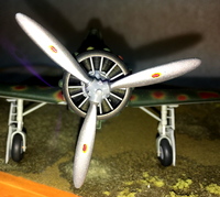 I built and painted the prop without fanfare. The forward faces of the blades were painted Vallejo Metal Color 77.701 Aluminum, the back faces were painted 70.603 Panzer Gray Surface Primer, and the hub was painted Dark Gull Gray. I attached the blades and adjusted the pitch until they were all equal. The decals were applied and the forward faces of the blades sealed with Future.
Unmask the leading edge of the cowling, slide the engine into the cowling, and secure it with super glue. Attach the assembly to the fuselage, making sure you have it straight and centered. An easy trick is to super glue a small piece of Evergreen sheet styrene to the engine's mounting surface. Clean the paint from the forward end of the fuselage, and you can use liquid cement to attach the power egg and allow for adjustments. Of course, you can also use super glue or epoxy, pick your poison.
The detail parts (landing gear, landing gear doors, etc.) were painted in the relevant colors using the kit instructions and reference photos as a guide. They were added to the model and allowed to set. I prop the model up on a few paint jars to allow the landing gear to stay set with the proper sweep and rake angles. Depending on your preference, you can use White Glue to install landing gear and ordnance.
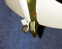 Over the time I have been working on the model, some parts got lost, misplaced, or broken. The tail wheel fork broke in two, and I misplaced the loose piece. So, I used some thin brass sheet to fashion a replacement. Make that two...no, three. I would make one that works, glue it on, and then it would break off and fly into the time warp under my workbench. The third time was the charm, although it, too, would come loose several times before I attached the model to the base.
I lost one of the kit gun barrels, so I scratchbuilt replacements using the remaining barrel as a guide. The replacements were fashioned from Evergreen rod. I drilled some 3/64" rod sections—short sections were drilled through, longer sections were drilled about 1/8" deep. The short sections were beveled to simulate the muzzle extensions. A short section of .020" rod connected the two larger sections. Once again, I would up making several of these, since I lost a few. One actually had the audacity to fly out of my tweezers as I was painting it! I painted the barrels with Vallejo's Panzer Gray Surface Primer and allowed them to dry.
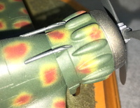 I sanded the aft end of the barrels to match the contour of the nose, and used Canopy Glue to attach them, making sure they lined up with the depressions in the cowl flaps. Once the initial application of glue dried, I used more Canopy Glue diluted with water to fill any gaps between the fuselage and barrels.
The venturi tube also went missing, so I took a section of 3/64" Evergreen rod, chucked it into my motor tool, and turned it against a file until I got an acceptable hourglass shape. I cut the venturi to length, and then drilled a tiny hole in the side of the venturi. I super glued a short length of fine wire to replicate the tubing that connects the tube to the plumbing inside the airplane. A small hole was drilled and the venturi was installed with a dab of Canopy Glue.
My final finish of choice lately has been either Vallejo Matte Varnish or Liquitex Matte Varnish (they're nearly identical products). Beware, though, that both products dry to a full, dead-flat finish and it can be easy to overdo them. I use the full flat only when I'm depicting a well-weathered machine. My usual practice is to take the bottle and turn it over once or twice to only partially mix the flattening agent in order to yield a semi-matte finish.
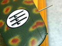
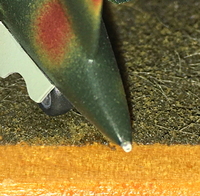 Pitot tubes were made from sections of hypodermic tubing, super glued into the indicated locations on the wingtips. The final details were position lights. I drilled a shallow hole in each wingtip, installed a short length of .020" Evergreen rod, and painted it to match the wing. The tips were painted silver, and when dry, lenses were added using a small dab of Canopy Glue. When the canopy glue was dry, the lenses were painted clear red or green as needed. When the paint was dry, a drop of Future sealed them. For the tail light, I sanded the point of the aft fuselage to a flat, painted that silver, and then made a lens from Canopy glue.
 The prop was installed with a dab of Canopy Glue. It was the final part added to the model.
I used a craft store plaque as a base. I sanded and finished the base with spray shellac, then glued felt to the bottom of the plaque. I used Woodlands Scenics' ground foam turf and static grass to landscape it. I first masked the base to contain the groundwork. The ground cover was sprinkled on to the base and then locked into place with Woodlands Scenics' Scenic Cement applied with a pipette. A tip—if you have problems with the cement beading up on the ground cover, mist a bit of Isopropyl Alcohol over the ground cover first to wet it—the alcohol makes it "wetter" that water, and the cement will soak right in. Let the ground cover dry and remove the masking.
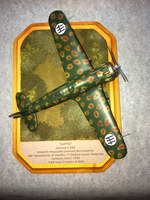 I made the placard for the base using card stock. I typed up the legend in my word processing program and printed that onto card stock. It was cut to size and shape, and attached to the base with 3M spray mount. This is a rather simple placard, but you can make them as elaborate as you wish. You can add squadron insignia, maps, or other graphics. A nice touch that I sometimes employ is to stick the placard to a bit of mat board (available at the local crafts store—some stores sell the off-cuts from their framing department in bundles), then attach that to the base. The added thickness of the mat board lends a more finished look to the placard.
The canopy was unmasked, and the model was attached to the base with a few dabs of Canopy Glue. And, with that, a 15-year odyssey comes to an end.
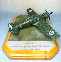 This was an enjoyable model. There were a few times that I had to backtrack, but I attribute this more to a loss of momentum than I do to anything about the kit itself. I got to try new techniques and refine techniques I had learned earlier. I dealt with the good and the bad equally. My final tip—if things go wrong, STOP! Don't fly the model into the nearest wall, or the floor, even though the temptation is there. Instead, set the model aside for a day or two—or a week, or a month. Most problems can be solved easily once you take time to analyze them and formulate a game plan, and the best way to do that is to give the model a rest. Take a break. Get your head right. Think. Once you have a fresh outlook, you'll find the fix isn't anywhere near as difficult as you thought, and only takes a few minutes.
References
Aero Detail #15: Macchi C.200/202/205 by Carmine DeNapoli and Scott T. Hards, ©1995 Model Grafix. ISBN-13 978-4499226516
Osprey Aircraft of the Aces #34, Italian Aces of WWII by Giorgio Apostolo and Giovanni Massimello, illustrated by Richard Caruana, ©2000 Osprey Publsihing. ISBN-13 978-1841760780
The "Stormo! Magazine" website
