
Trumpeter 1/32 FA-18E
By Steve Gallacci
Huge pile of plastic, artfully packaged in a huge box is the first impression. This is a big and complicated kit of a big and complicated subject. And for the first time in my review building, a kit that is proving to be a real challenge to assemble. This should not be taken so much as a criticism of Trumpeter, but more a matter of a complicated design bravely attempted and largely succeeding.
However, a bothersome design weakness of the kit, common with other Trumpeter products, is in a couple of option features which are not really engineered to be optioned. In this case, the wings can be folded or extended, but extended requires extra creative effort from the modeler. Similarly, the refueling receptacle is not really designed to be closed, though theoretically could be built that way.
On the other hand, a feature that is particularly good, are cast metal re-enforcements for the landing gear, sandwiched between the main halves of each strut. They are very strong and fit stoutly into the fuselage.
An ongoing controversy for many Trumpeter kits is the inclusion of "rubber" tires, hated by some, loved by others, without an option of plastic alternatives.
There is one mystery detail in Step 24. The instructions indicate that a photo-etch strip of metal, part PE5, needs to be glued into the nose gear door, part H24. The mystery is two-fold, why would you need to have the complication of the photo-etch detail? And while the instructions indicate that the photo-etch goes on the inside, the parts look like it ought to go on the outside. I put mine on the outside. Then, a web search found that the real thing would be a fine perforated panel, and on the outside. So in the end, for a really proper duplication, the panel ought to be clear plastic with a very fine pattern decal on it, being too fine for conventional photoetch, or even just tinted clear plastic.
There is a minimum of photo-etch in the kit otherwise, just the belts for the pilot's ejection seat.
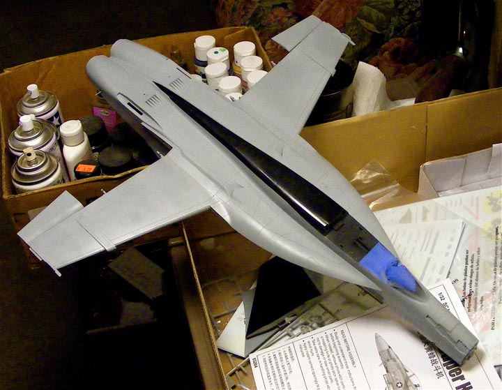
The model as configured without a lot of wing stores, does need nose weight. I planned to not display the radar, so would fit the nose with weights, but didn't check the fit first, and discovered a bit of mis-fit. An unfortunate last minute discovery. Alternately, if you just hang the big belly tank on it, the tank nose can be loaded up with some weight.
Most of the rest of the kit is actually fairly straight forward, wings and control surfaces are simple assemblies, only the leading and trailing edge flaps have any joints that need some attention of putty and sanding, and these are all on the undersides, so you could get sneaky and ignore them. A similar joint runs along the underside of the large LEX. An other seam that really needs attention, and particular care in assembly to avoid making worse is where the rear fuselage side, top and bottom all come together. No slight to Trumpeter on that, as it is simply a very awkward assembly point. The forward fuselage also has a potentially troublesome seam, and extra attention should be paid to that.
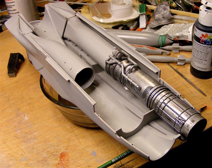
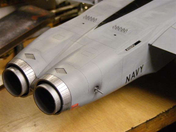
The engines are sort of detailed, but not so well done to really display, and the instructions are not so clear as to how to fit the details as they are on the engine bodies. The only real value of the engines are that they provide a good compressor face for the intake and burner details for the exhaust. However, as there is no provision to display the engines, it is all moot anyway.
Another little lapse is the navigation lights on the upper surface of the LEX, a simple scribed outline on the kit and a bit tricky to paint. It would have been easy enough to do it as a decal or a clear insert. As is, I'd recommend deepening the scribed outline to make filling in the color a little easier.
Recommended alternate assembly sequences and details to deal with.
Step 3
Step 7
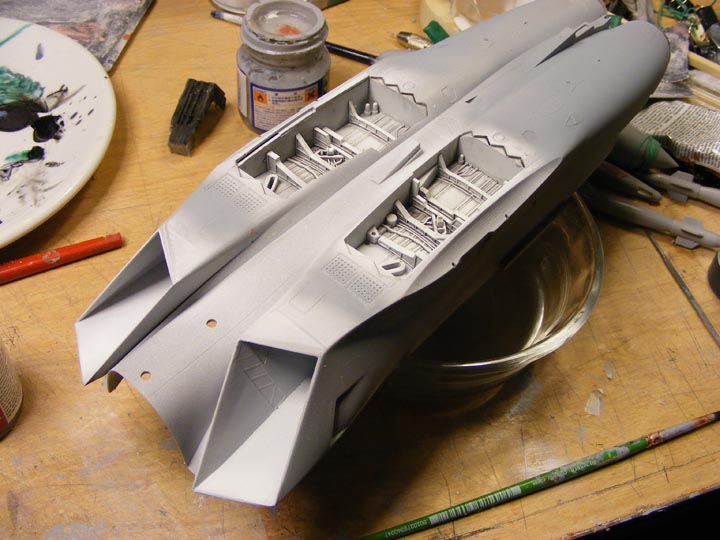
I was going to suggest gluing the lower forward fuselage assembly to the lower center fuselage and clean up any joints, but the fit to the lower fuselage is actually pretty good and the joint is easily accessible. However, the forward fuselage to upper fuselage joint fit is more critical, and better to have the the forward fuselage group loose for installation at that step. Nevertheless, the next thing to do is glue the inner sections of the intake scoops, parts F1 and F2, to the fuselage sides, parts A2 and A8 before gluing the fuselage sides to the lower fuselage, and only glue along the outer edges, allowing the scoop to be a bit loose to adjust for later installation to the LEX and upper fuselage.
Steps 8 to 17 and beyond
If you intend to build the kit with the wing extended, glue the lower inner and outer wing halves together FIRST, allowing the glue joint to properly harden before doing anything else, as it is a simple unsupported butt joint. Then I would recommended adding some supplemental re-enforcement to the joint, if not a full span spar, before attaching the upper wing halves. I would recommend NOT fitting the control surfaces to the wings until after the wings and fuselage have all been assembled. There are some joints that need attention and clean up, and the surfaces would be in the way if they were fitted. If the wings are extended and the control surfaces are to be set in the level position, I'd recommend the inner and outer sections should be done at the same time to allow adjustments between them. I set the outer sections first and then later found there wasn't enough slack in the inner sections alone to align them neatly.
Step 18
Step 22
I'd recommend fitting the wings to the upper fuselage first, as they DO NOT simply plug into the fuselage sides. The joints can be fought with (you will almost certainly need to fight with the exact alignment of the wing to fuselage joints) without the complication of the lower fuselage.
Before joining the upper to lower fuselage, I'd REALLY recommend adding some kind of re-enforcement to the elevator mount points. The kit parts would have the elevator base stub plug into a simple hole in the fuselage, not nearly enough substance to hold the considerable weight of the large slabs of the elevators. I used a piece of heavy acrylic, CA glued between the inside of the fuselage and the engine, to use as an extra glue surface and mount for a steel pin that will go into the elevator base stub. The forward fuselage group will fit into the lower fuselage and most of the LEX surface without any real problem, but where things could get tricky, and where fit is critical, is the forward edge in front of the LEX. Test fit, test fit, test fit.
Step 26
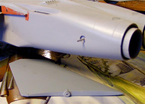
The refueling probe looks okay, but the recess for it is unconvincing, and if you want to build it closed, the door, part F11, needs all the back detail removed and lot of trimming to fit.
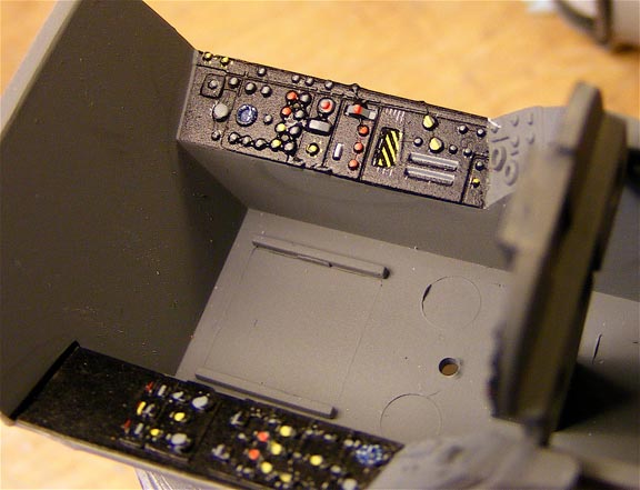
As with other recent trumpeter kits, the decals for the cockpit side and front panels will conform to nearly all the lumps and bumps. However, there are a couple particularly prominent details on the main instrument panels that ought be trimmed down, otherwise the decals will tend to "tent" on the high spots and risk distorting as they lays down. Also, the side panel decals were apparently printed before the side panels were fully tooled, and that portion of the decal detail is just a block of color. You will need to hand-paint that part of the panels. The number call-outs in the instructions versus what is actually printed on the decal sheets don't always match, but not so much to be a problem, as the instructions are otherwise fairly clear as to where things are suppose to go. A small disappointment regarding all the decals that go with the ordinance is no color bands or stencils for the two AIM-9s. A little tip, the decals for the electro-luminescent strips are not the same length and cannot be interchanged between the locations and the printed panel outline around them is inappropriate and could be cut away.

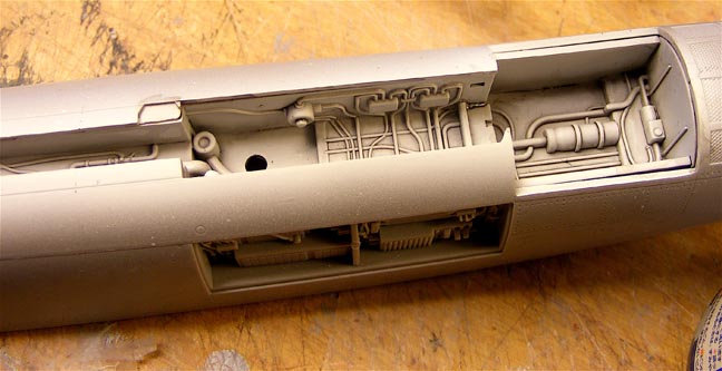
The kit instructions have named colors to go with manufactures color codes, handy if you don't have access to the specific paints. However, the instructions are rather limited in details and are incorrect or miss some call outs entirely. For example, there are open avionics bays on both sides of the fuselage, but no color instructions for them at all. The color three views of the overall model don't clearly show the demarcation of the upper dark ghost gray to lower light ghost gray (partly due to the limited contrast of the colors, but some artistic license could have been done to make things clearer) and the radomes on all the machines are called out in "radome tan" when they appeared to be light ghost gray in real life. I would strongly recommend doing some supplemental research for painting and marking details, even before starting the kit, to make sure you are prepared to take care of those features as you proceed.
Mounting the ordnance is another thing entirely. Presumably, the weapons sets are a common product for many 1/32 modern US aircraft, but the mounting details on many of the items don't match the FA-18 kit. While the kit instructions have a diagram to show which pylon carries which weapon, some of the kit parts are not so clear as to exactly how some of them are positioned on the pylons. Specifically, the AIM-120 + rail assemblies are suppose to fit to wing pylons, but exactly where on the pylons? And the AIM-120 fitted to the fuselage AIM-7 mounts have carry brackets, but where exactly on the AIM-120 body do the brackets set, and at what angle relative to the fuselage? Similarly, the mount pins on the pylons don't match the mount holes on the racks, bombs or missiles. Then, again, the previously mentioned discussion of appropriate weapons for the model also point out that the load diagram doesn't reflect actual load arrangements.
With a rewritten instruction sheet that includes more painting information and clearer part installation details, possibly a decal sheet with some adjustments and corrections (would a multi-part <middle and two sides>dorsal spine decal along with the current cheat line+painted dorsal option be possible?) and a few weapons that better match actual operational use, this kit would be more accessible to more modelers and make for a truly outstanding kit.
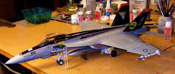
Notes on the finished model as photographed
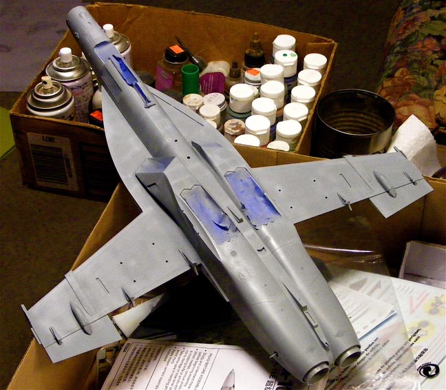
The overall finish is Model Master light and dark ghost gray enamels, the light ghost gray had a little white added to increase the contrast along the demarcation, then some Gloss-cote to provide a hard finish and help with decal application, then a coat of Dull-cote to even out the finish a bit, The black dorsal spine is not quite correctly laid out but was done with Alclad gloss black base, as were the fins. The added red inner fin tips were a mix of Humbrol acrylics from the Wallace and Grommet "Antipesto" van kit. The white parts were done to best effect with a base of Model Master flat white enamel and then a finish coat of Tamiya gloss white acrylic. Too late I found that the engine intakes were suppose to be light ghost grey around the mouth. The nose landing gear strut scissor lower half is missing on the build, lost while being handled.
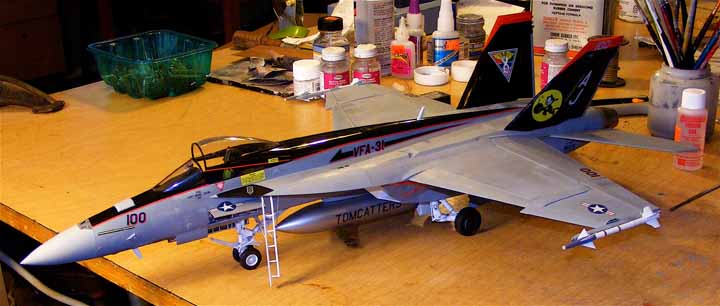
Finally, I have decided I really don't like applying long thin decals, like stripes and such. And the kit build suffered for it. Were I to try to do this again, as much as I also don't like masking off lots of painting details, I'd rather paint those things. It is a finishing feature I did not enjoy, entirely NOT a fault of the kit or the kit decals.