From Internet Modeler
Yet another Accurate Miniatures 1/48 North American B-25B Mitchell *
By Sanjeev Hirve
Jul 1, 2001 - 7:36:46 PM
* With apologies to the creators of YACC
|
|
Introduction
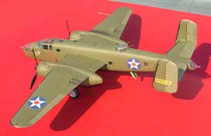
The B-25 Mitchell was one of the most popular medium bombers of World War II, seeing action in every theatre of the war. Named for the father of modern aerial bombardment, General Billy Mitchell, it attained fame for its use in Doolittle's daylight bombing raid on Tokyo on April 18, 1942. Sixteen B-25Bs took part in the raid, taking off from the carrier USS Hornet, and flying on to land in China. The USAF museum and the Navy Historical Centre web sites have extensive coverage of the plane and the raid.
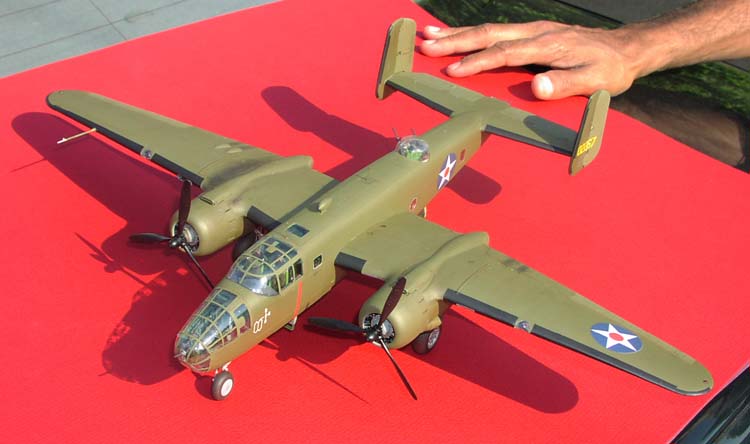
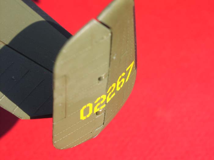
I chose to build this model because I love Accurate Miniatures kits. As with their other kits, it is obvious that a lot of research and effort has gone into the design of this kit. The kit itself offers parts to build several variations, and decal markings to build any of the Doolittle raiders. I chose to build the Doolittle raider named "TNT", tail code 02267. I chose this plane because of the historic significance of the raid, and selected one with sober nose art, since the more famous ("Ruptured Duck") and colourful ("Hari Carrier") planes of the mission tend to be popular subjects for the modelers.
As references, I used Squadron's "B-25 Walkaround" and a plethora of web pages. Unfortunately, most of the photographs are of later B-25 versions - I found very few usable photographs of the Doolittle raiders or the B-25B. However, many of the reviews and discussion forums (e.g., https://www.clubhyper.com/forums/forum.htm) provided valuable details and timely help.
 Many excellent web reviews have been written of Accurate Miniatures' 1/48 kit B-25B Mitchell. In this build up review, I attempt to emphasis some different aspects; namely, combining after market components with the kit, and using some techniques to make some of the model parts.
After Market Accessories - The Verlinden and Eduard detail sets I used the following after-market accessories for the kit; the Verlinden Detail set (#1574), the Eduard photoetch detail set (#48323), the Eduard Express mask (#XF060) and the True Details Fast Frames (#41312). I decided to purchase these accessories along with the kit. I like to use accessories for the sheer fun of it - they make the build more interesting, the instructions more challenging, and in most cases, a better finished model.
There is considerable overlap between these two sets. The Verlinden detail set consists of resin parts and a photoetch fret. The quality of the resin parts is excellent. In most cases, they definitely improve on the kit parts, though the axial length of the engines is short by about .020". I used calipers to measure the length of the kit part, and shimmed the engine with plastic card. The Eduard set has three frets of good detail, one of which is devoted to the bombs. Both the Eduard and the Verlinden frets include the tubing for the engine spark plugs, however, I chose the Verlinden photoetch for several reasons. Firstly, the Verlinden brass is thicker and hence easier to work with, especially for the complicated shape of the engine wiring. Secondly, the Eduard photoetch part for the engine has finer detail but is incorrect: the wires are too short to reach behind the cylinders, and every alternate cluster consists of three wires - in reality every cluster should contain two wires. I based my assumption on several photos of the Wright R-2600 engine. In both sets, the circumference of the annular feeder ring is too short, and as a result, the tube clusters do not align with the cylinders (the Eduard part is worse in this respect).
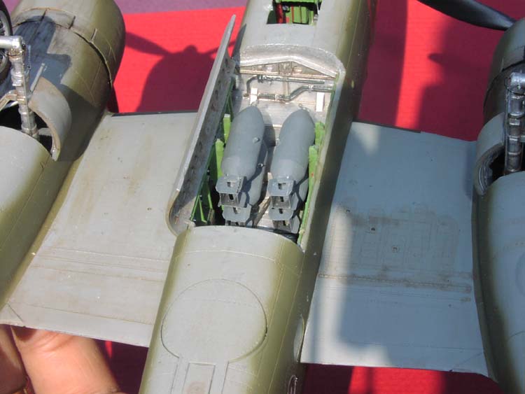
If you are building the Doolittle raider, almost half of the Verlinden set will be for naught. The Verlinden set contains an ample supply of ammunition boxes, ammunition cans, oxygen bottles and fire extinguishers. I put these in but felt guilty about it because the Doolittle raiders were supposed to have been severely stripped to reduce weight. Reluctantly, I left out the Norden sight, whose inclusion would have been too flagrant a violation of authenticity. The tail guns and the ventral turret guns were similarly discarded. The Verlinden set also contains panels that I suspect are not found on the B version (either Accurate Miniatures or Verlinden, is wrong here). If installed, the turret cover would not have fit - the parts for the dorsal turret being too big.
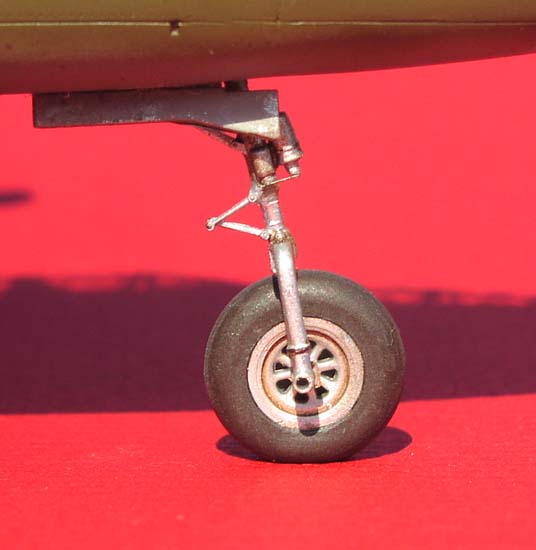
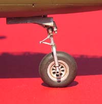
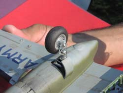
 For the pilot and co-pilot seats, I used the Verlinden resin parts instead of the Eduard seats because the former appear to be accurate. The V-links for the strut oleos are accurate for the main gear, but the one for the nose gear is too big. Similarly, parts 62 and 54 for the dorsal turret are too big. Both sets improve on the kit-supplied Brownings. The Verlinden set has a good body, while the Eduard brass provides a perforated barrel sleeve and other details.
Overall, the Eduard set provided very good detail, but again, I ended up using only about 30-40% of the parts because of duplication with the Verlinden set, and because I built a Doolittle version, which has fewer guns and only four bombs. The most valuable contribution of the Eduard set is to the cockpit interior. In my opinion, it is still very good value for the money, even if you do not care for the extra options it offers.
Eduard Express mask
 If I had known that Accurate Miniatures includes pre-cut masks with its kit, I would not have ordered the Eduard Express masks. Having said that, I must state that the Eduard set is better designed. It employs a combination of masking and liquid mask for panels with compound curves, which definitely gives a much better fit. The set seems to contain mask for most of the parts of the clear part sprue, i.e. the mask can be used for other variants of the B-25. However, neither the kit nor Eduard includes masks for the dorsal turret – a puzzling omission. One has to be careful, though, to burnish down the masking strips properly. I found that the liquid mask shrank a bit on drying and peeled the masking loose. Except for that, the Eduard and the kit-supplied masks are equally crisp and equally easy (or difficult) to handle.
True Details Fast Frames
With two sets of masks already in hand, why did I buy yet another canopy detailing set? Answer - I needed the Fast-Frames for my heat-formed canopies. In my opinion, the Fast Frames cannot be used with the kit canopy parts because the latter is already moulded with raised frame details. However, if you make your own canopy, it's a godsend; the thickness of the Fast Frames is just right and much more realistic than the kit part.
Messing around
I deviated from a standard build in various areas, the main one being the replacement of the kit-supplied clear parts with heat-formed parts. Following is a medley of topics, covering various modifications I made to the kit, techniques I used and mistakes I made.
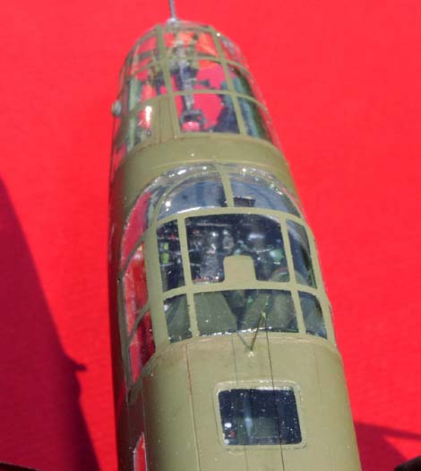
Canopies
 I put in a lot of effort building the plane's interior. This motivated me to replace the kit canopies with something more clear and distortion free. The kit parts are good but being moulded, they introduce some distortion. That, plus the thickness combine to obscure the view of the interior.
After much thought, I decided to heat-form my canopies. The following is a description of how I made replacements for the cockpit canopy, bombardier's canopy, nose cone, dorsal turret, tail gun glazing and the landing light covers in the wing leading edge.
I started with .010" ThermaForm sheets from Squadron, but moved on to .010" clear Butyrate sheets from Micromark. In my opinion, the latter is a better material for heat forming, and cheaper to boot. Initially, I used the kit part directly for the mould, but quickly gave it up for various reasons. First, the kit part distorts under pressure. Secondly, the raised details are reproduced onto the sheet; these details are less crisp, and the framing is wider. Thirdly, it messes up the kit part, leaving one without a fallback. Finally, the dimensions of the formed part come out incorrect; about .010" bigger in all directions.
So, onto Plan B: Make the mould with clay.
 I used the following technique for all the canopy parts. I took Sculpey clay and pressed it inside the kit part. To protect the part, I lined it with Saran plastic food wrap. I stuck a 10-inch Gutter nail in the clay, and baked the whole thing. The clay must be baked right according to the directions on the package. Bake it too much and it becomes crumbly, too little and it plies under stress. Once the clay had hardened and cooled, I checked the surface for creases and pits, filled them with Squadron putty, and sanded the surface down to a medium finish. I mounted the mould in a bench vise and pressed down a butyrate sheet on it, while a helper heated it evenly with a heat gun. As the plastic gave, I pressed it down and under the mould while the helper kept up the heat, albeit at a reduced level. Gloves are needed to protect your hands. Mittens simply won't do, because you need a good, firm grip on the plastic. The kit parts are roughly .020" to .025" thick, so I formed two layers of .010" sheet, discarding the inner layer. The resulting outer layer is thinner than the kit part and pretty close to the correct dimensions.
I found the heat gun method to be better than the candle-and-smash approach because it gave me a lot more control and time to work the plastic and was more forgiving of mistakes. Even so, I had a success rate of about 1 in 3. The only thing that kept me going was assurance from other modelers about their own poor success rates.
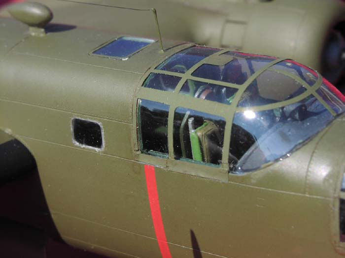
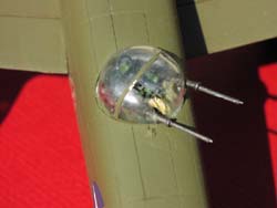 The first part to be produced, the dorsal turret, was the easiest. I stuck it on a base of .020" styrene, then used super glue to stick it to give it rigidity. This promptly fogged the plastic, and I spent a lot of time polishing the inside with a toothpick dipped in thinner. A coat of future brought it a half-decent finish. Making the next part, the cockpit canopy, was a tedious task. I used the kit part to trim the formed sheet to the approximate size. After that it was a slow and laborious process of repeated trimming, sanding, and fitting. Test fitting is complicated by the fact that the part is extremely flexible; it slips all over the place. To overcome this problem, I marked the center points of the canopy and the fuselage with bits of tape. This helped somewhat to align the parts for fitting. At the cockpit bulkhead I formed a "shelf" for the canopy. I made this with a 1/16" square brass stock bent to the proper shape and glued it to the bulkhead with a clearance of about .010". To attach the canopy, I decided to use epoxy for its many advantages: quick setting, strong, non-melting and non-fogging. The strong bond was deemed necessary in case I decided to mask the canopy. The gluing process went off with hardly a hitch. The only problem with epoxy is that it cures bright and shiny; the bead is very conspicuous, and, being on the inside, there was nothing I could do about it. On my next project, I plan to use Formula '560' Canopy glue from Pacer Technologies. This glue cures quite clear and has a strong and chemical resistant bond. Its only problem is its long curing time; the part has to be taped in place and glued one section at a time.
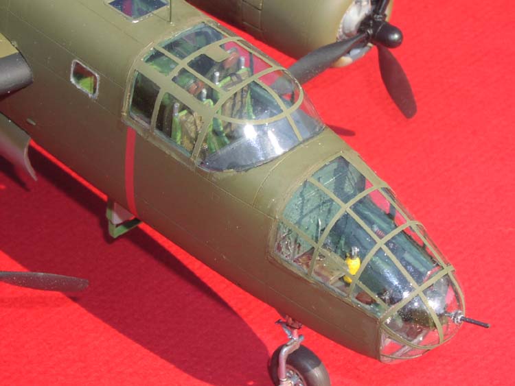
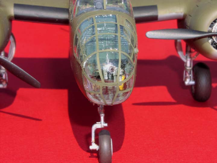
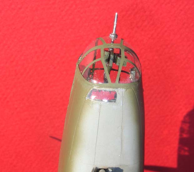
 The next parts were the nose cone and bombardier's canopy. They are the most challenging since their edges are glued to each other along the top. At one point I toyed with the idea of forming the two parts with a single mould, but this would be one complicated mould. Given my success rate with heat forming, I shelved that idea quickly. I had to trim-fit the two parts concurrently, taping one part to the nose while I trimmed and test-fitted the other. I refined the fit by alternating between the parts. After many hours of trimming, I still could not get the edges to abut each other precisely, so I gave up and glued them with a small overlap. The overlap is visible but mostly disguised by the framing, so it doesn't look too bad unless you inspect it closely. The bombardier's canopy has a panel that swings out (as an emergency hatch, I think). I briefly considered cutting it out and attaching it in the open position, but... maybe next time!
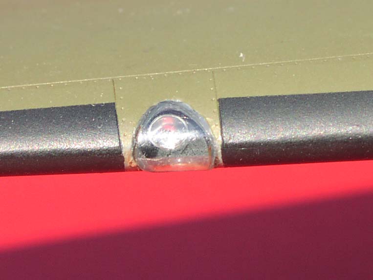
 It was all downhill after that: the tail gun canopy and the light covers were easy. I used HO railroad lamps for the landing lights. To simulate a light bulb, I dug a small hole in the back of the reflector with a knife and applied a dab of paint.
I chose Fast Frames over canopy masks for three reasons. First, Fast Frames reproduces a raised frame realistically; the only way to do this with a mask is to apply multiple coats of paint. Secondly, with masks, I have to worry about proper positioning, which is virtually impossible to attain. Thirdly, I was worried about tearing the canopy loose when I pulled off the masking. As I said, the Fast Frames were a godsend.
 I am partially satisfied with the results, which you can judge for yourself from the photos. The glazing is very clear, so I achieved my main objective. The whole thing looks like the handiwork of an inebriated tinsmith whose only tools were a hammer and a bigger hammer - maybe they were in a hurry to get the planes ready for the raid! In retrospect, a little more patience and careful trimming could have given better results.
Windows
As with the canopies, I was strongly motivated to build clearer windows to afford a better view of the plane's interior. Most of the window glazing is flat. I used transparency sheets to make most of them. On the plus side, they are very thin, about .005". On the downside, they are not easy to work, are slightly tinted, and are not easy to glue. A tradeoff for the thinness is the difficulty in sanding the edge.
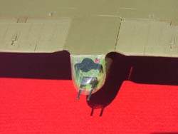
 I also tried Micro-glaze from Micromark. This is very easy to use, but the results are iffy. If I use too much glaze, it dries to an uneven surface. In any case, it ends up thicker around the edges, distorting the view. The best use of Micro-glaze was in the observation slot in the chin of the bomber. This window has a simple curve (in one dimension). I taped an acetate sheet on the outside and applied the Micro-glaze from inside with a toothpick. Twelve hours later, I peeled off the acetate carefully. The glaze was still a little hazy, but it dried to clear after a few hours. Only time will tell how many years it will last.
The material I am happiest with is K&S .020" Vivak clear sheeting from Micromark. This material is stiff, exceptionally clear and free of distortion. It is also easy to work. Being thick, it is easy to press-fit the piece into the openings, avoiding messy glue. The only problem is that its surface finish mars easily, so one has to be very careful sanding it. This material is ideal for flat glazing, but I have not yet tried to heat-form it.
Engine Cowling
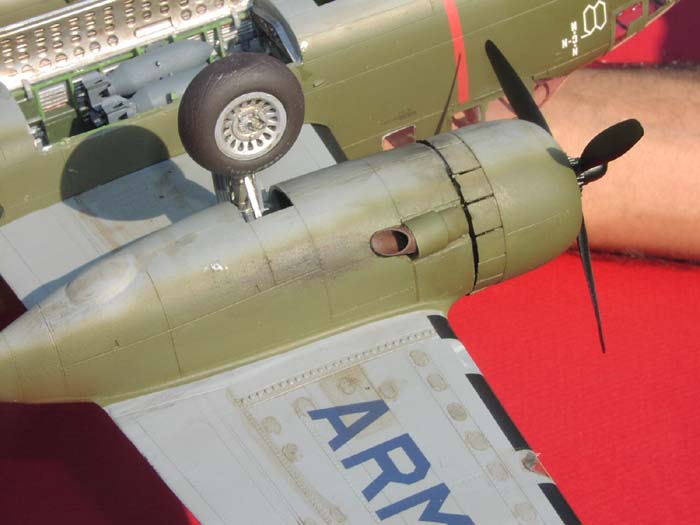
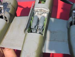
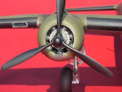 The kit part for the engine cowling required some sanding on the inside to accommodate the Verlinden engine. I decided to use my Dremel tool to speed up the work, but it ended up slowing me down. The tool melted the plastic through in a couple of places, but luckily I could repair most of it by filling it with CA. The cowling now has a very realistic dent in it. The cowling has venting skirt flaps that are positioned closed. I like the flaps positioned open, so I used the following method. First I cut through the between the flaps with a #10 Exacto blade to separate them. Next, I sanded their insides to a reasonable thinness. I scored the inside's joint line and carefully bent each flap outward about 20 degrees. I did this to all the flaps except two each at the top and bottom, which I left untouched for attaching the cowling to the engine mounting. I also cut out about 80% off the face of the engine pod (the firewall?) to give it a more open look.
 The exhaust pipe supplied with the kit does not look right. It does not even look like the one in their instruction booklet! I made it with 3/16" styrene tube stock and sanded its inside to the appropriate thickness. I cut off the pipe from the kit part but retained its sleeve.
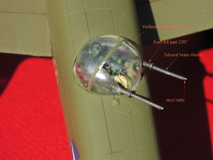
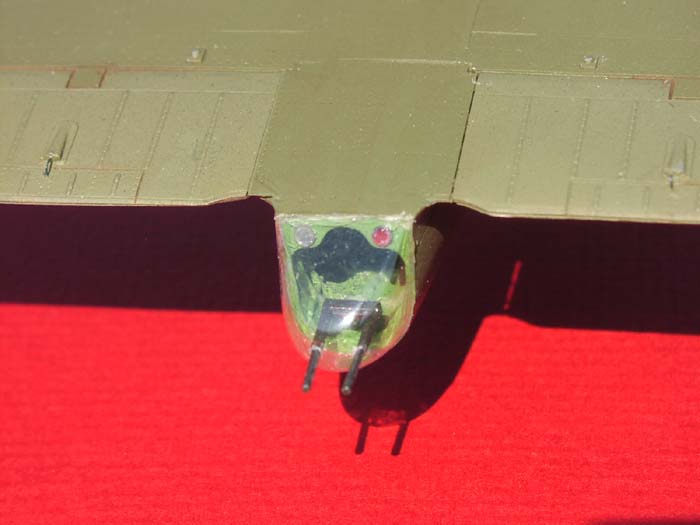
Guns
I constructed the guns using the resin body from Verlinden, barrel sleeves, other brass parts from Eduard, steel tube, and a little bit from the kit-part! This yielded much finer detailed guns. I made the barrels of 0.5 mm steel tubes from Minimeca. Eduard photoetch provided the barrel sleeves. For the sleeve, I rolled the brass on a drill bit of the proper diameter. I also noticed that annealing the brass gives it the perfect "Blueing" effect, which meant I did not have to paint the sleeves and risk clogging the vents. Note that the Browning from Verlinden is not identical in length to the gun in the kit, while the Eduard barrel sleeve is. So the final result was made up of the resin body from Verlinden and the brass barrel sleeve from Eduard, connected together with the spool shaped bit from the kit, where the barrel joins the gun receiver.
For the ammunition belts, I splurged and bought cast-brass 50-cal ammunition belts from Teknics (part # TK48061). While they are well detailed, it was not easy to bend the belts to the proper shape between the ammunition can and the feed slot. I lost a fair length of the ammunition to breakage.
Antenna
 I determined that the B-25B typically has a single wire antenna on its back. I decided to make it with stretched sprue - my first time with this material. I used the Eduard brass for the two posts, attaching them to the plane with epoxy. The kit part for the ADF housing is too big, and the antenna posts are too short. I had to sand down the ADF housing. I made the wire by stretching clear sprue. I was amazed at how easy it was to stretch it to a thickness of .004" or less. I painted the wire black by running it through the tip of a black permanent marker. It needs 2-3 passes to get it really black. Next I carefully cut a length about 1/32" longer than needed. I placed a dab of thick CA on the top of the post and carefully jockeyed the end of the wire onto it. Repeat at the other end. At this point, the wire sagged significantly, so I let it dry for 12 hours. I then held the plane upside down and passed a 25-watt soldering iron under the wire, moving it slowly back and forth. After about 30 seconds, the sprue suddenly snapped taut: easy as falling off a log. Well, not actually... It took three attempts to get it right. In my first attempt, I picked the wire off a soft surface with my tweezers, and put a noticeable kink in it. No problem, I thought that the heating would fix it. The first pass tautened the wire but not enough to remove the kink, so I gave it the soldering iron treatment again, and the wire came loose from its mooring. During the second attempt, I got a bit impatient and brought the iron too close to the wire. When the wire snapped taut, it bounced against the iron, and melted. The third attempt avoided the above mistakes.
Tail fins
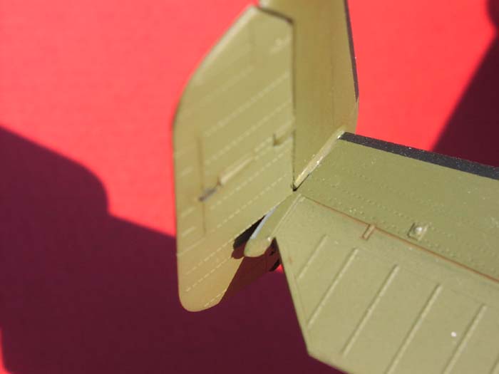
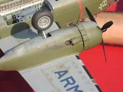
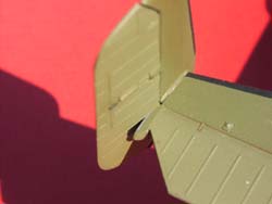 I decided to cut out and reposition the rudders, another first for me. I have considered attempting it before but never took the plunge. I separated the rudder with a straight cut, destroying the hinge points. Then I cut out the notches for the hinges, while I built up the hinge on the tailfin with laminated plastic sheet. To make up for the plastic lost to the sawing, I glued plastic strips to the edge of the rudder and sanded it down to a rounded edge. The tail fins turned out to be a bad choice; the ailerons or elevator would have been easier. The problem is the kit shape. The joint of the tail fin and tail plane is shaped such that it leaves an ugly yawning gap when the rudder is offset. Moral: choose your dragons wisely.
De-icing boots
 The de-icing boots look innocuous, but takes ages to mask if you mask it my way. I painted the wing and then the boots. I have seen photos of other builds where the boots were painted first. Their end result looked fine even though they applied a lighter color over black. The problem with masking the boots is the complex curves at the ends of the boots: the filets at the engine cowling and the root of the tail plane. The boots also extend in a curve at the wing tips and the tailfin top and bottom. I tackled these curves by making a template from stiff plastic sheet. I need only one template for the wing tip, and two for the tail fins since the template can be inverted to trace the other face.
Seams
I filled most seams with CA glue. The technique is simple and fast. Fill the seam with thick CA, apply CA accelerator over it, let sit for a few minutes, and then file it down with a rough file. Once the crust is broken, revert to smoother file and sandpaper. I could fill out the Grand Canyon with this technique! In a few places I used Gunze Mr. Surfacer 500. While the seam looked all right to start with, it inexplicably developed cracks when the plane was finished and painted, when it was too late to do anything. I suspect that some of my coats must have dissolved the filler.
Decals
 On the whole, the decals in the kit are very good quality. They set very well, and the colours are in good register. I had no perceptible silvering and the surface reacted well to Testors Dullcote, blending the decal well with the rest of the surface. I got complacent. Too late I noticed that one of the insignia was out of register and left a perceptible white half ring on the edge. Too late because the decal was nice and wet by the time I noticed it. Always examine your decals carefully. Luckily I could cover my mistakes with some paint.
Conclusion
The Accurate Miniatures kit has excellent exterior and interior detail. The decals are of a very good quality. The seams require very little filling, though I did have some trouble with the engine pod and the bombardier's compartment. The Verlinden and Eduard detail still manage to improve on the kit. Both sets have their areas of strength, but there is a fair amount of overlap, and two sets is a bit of an overkill.
References
-
Walk Around B-25 Mitchell, by Lou Drendel, published by Squadron/Signal publications (ISBN 0-89747-379-5). This book provides good detail for the undercarriage, engine and cockpit of the B-25B.
-
Accurate Miniatures has a good online build review on their web site.
-
Internet Modeler carries a review in their March 2000 edition.
-
The Hyperscale web site has a review. The same site carries a review of theVerlinden detail set .
-
Modeling Madness has a kit review by Tom Cleaver.
-
Another very good review by Donald Granger. This review especially points out some errors in the kit.
-
For general reference on the B-25B, see the USAF museum web site.
-
The Navy Historical Centre has a big collection of photos of the Doolittle raid.
-
© Copyright 2023 by Internet Modeler